Implantable lead with braided conductors

a technology of electrical conductors and components, applied in the direction of insulated conductors, cables, therapy, etc., can solve the problems of affecting the performance of the therapy delivery element, affecting the service life of the patient, so as to achieve the effect of improving the service life and performance, reducing the risk of injury, and improving the service li

Active Publication Date: 2013-09-24
CIRTEC MEDICAL CORP
View PDF17 Cites 64 Cited by
  • Summary
  • Abstract
  • Description
  • Claims
  • Application Information

AI Technical Summary

Benefits of technology

[0008]The present disclosure is directed to a therapy delivery element adapted to be implanted into a living body. The therapy delivery element includes an electrode portion with a plurality of electrodes. At least one elongated lead body is attached to the electrode portion. The elongated lead body includes a stylet coil having a stylet coil lumen. The stylet coil extends within the elongated lead body and along at least a portion of the electrode portion. A conductor assembly with a plurality of insulated electrical conductors is braided to extending around the stylet coil and to electrically couple to one or more of the electrodes. The conductor assembly includes an inner lumen with a diameter greater than an outside diameter of the stylet coil. Axial elongation of the elongated lead body reduces the inner diameter of the conductor assembly. A low durometer insulator extends around the conductor assembly. A stylet sized to slide freely within the stylet coil lumen is provided for use during implantation of the therapy delivery element into the living body.
[0012]The present disclosure is also directed to an extension for therapy delivery element. The extension includes a connector adapted to electrically couple to a proximal end of the therapy delivery element and an elongated extension body attached to the connector. The elongated extension body includes a stylet coil having a stylet coil lumen. The stylet coil extends within the elongated extension body to the connector. A conductor assembly including a plurality of insulated electrical conductors is braided to extending around the stylet coil and electrically coupled to the connector. The conductor assembly includes an inner lumen with a diameter greater than an outside diameter of the stylet coil, wherein axial elongated of the elongated extension body reduces the inner diameter of the conductor assembly. A low durometer insulator preferably extends around the conductor assembly. A stylet is provided that is sized to slide freely within the stylet coil lumen during implantation of the extension in the living body.
[0013]The present disclosure is also directed to method of implanting therapy delivery elements in a living body. The method includes inserting a stylet in a lumen of a stylet coil extending through an elongated lead body of the therapy delivery element. The stylet coil is surrounded by a conductor assembly including a plurality of electrical conductors braided to form a generally tubular structure electrically coupled to one or more of electrodes at a distal end of the therapy delivery element. The stylet adds stiffness to elongated lead body during positioning of the therapy delivery element in the living body. The stylet is removed from the therapy delivery element, rendering the elongated lead body flaccid. The electrical conductors at a proximal end of the elongated lead body are electrically coupled to an implantable pulse generator implanted in the living body. An inner diameter of the conductor assembly is reduced in response to axial elongation of the elongated body portion.

Problems solved by technology

As a patient implanted with a therapy delivery element moves, some regions of the body may expand and contract, resulting in changes in length.
These forces may cause lead failure, axial migration of electrodes, anchor damage, or tissue damage.
The patient may experience pain or operational failure or performance degradation of the therapy delivery elements.
Increasing stretchability of a lead body can also increase the vulnerability of the lead body to flex fatigue, buckling fatigue, kinking, and crush.

Method used


Image

  • Implantable lead with braided conductors
  • Implantable lead with braided conductors
  • Implantable lead with braided conductors

Examples


Embodiment Construction

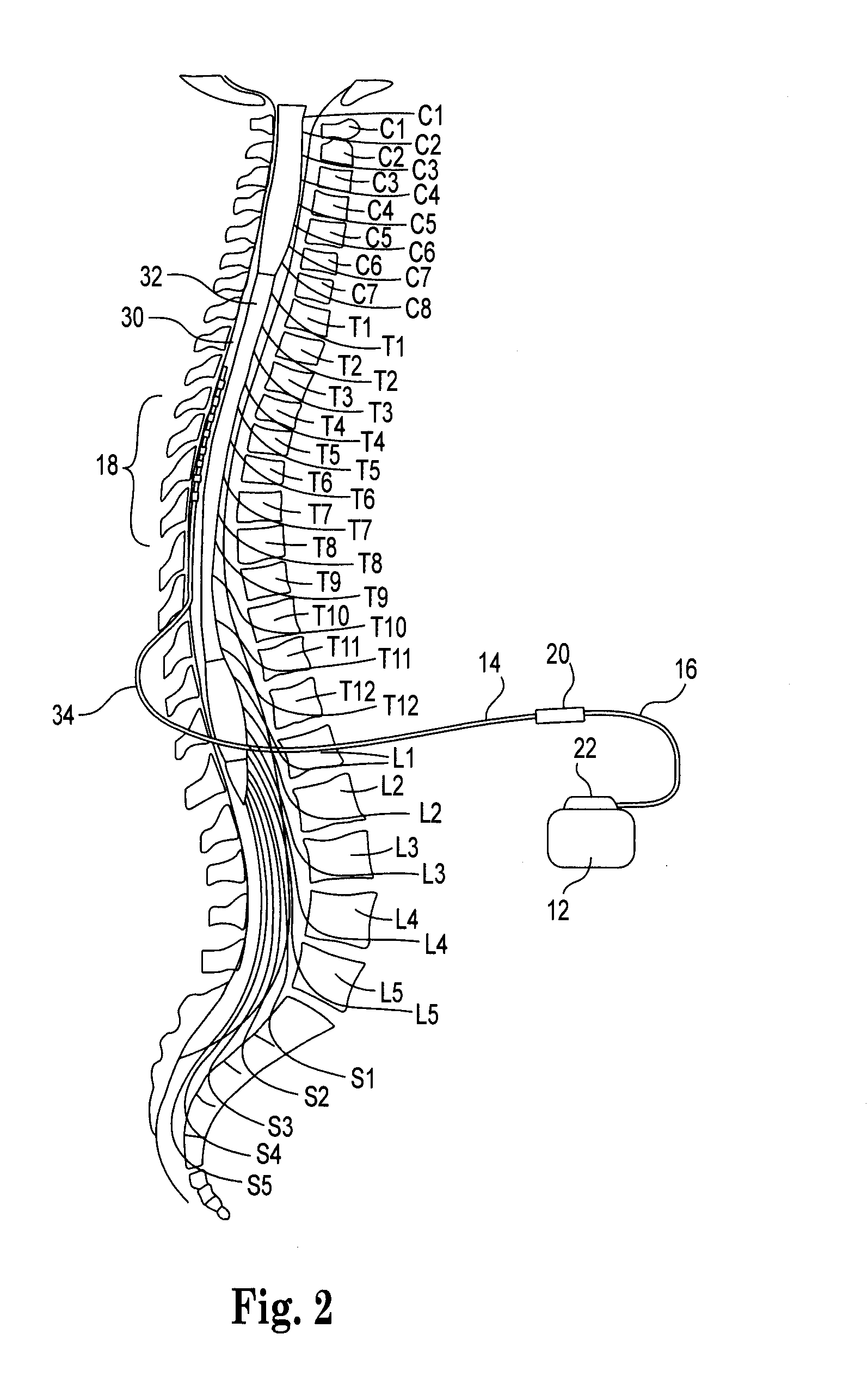
[0027]The description that follows relates to spinal cord stimulation (SCS) system. However, it is to be understood that the while the present disclosure lends itself well to applications in SCS, the disclosure in its broadest aspects may not be so limited. Rather, the disclosure may be used with any type of implantable therapy delivery system with one or more therapy delivery elements. For example, the present disclosure may be used as part of a pacemaker, a defibrillator, a cochlear stimulator, a retinal stimulator, a stimulator configured to produce coordinated limb movement, a cortical stimulator, a deep brain stimulator, peripheral nerve stimulator, microstimulator, or in any other neural stimulator configured to treat urinary incontinence, sleep apnea, shoulder sublaxation, headache, etc.

[0028]In another embodiment, one or more of the therapy delivery elements may be a fluid delivery conduit, such as a catheter, including an inner lumen that is placed to deliver a fluid, such ...


PUM


Abstract

A therapy delivery element adapted to be implanted into a living body. The therapy delivery element includes an electrode portion with a plurality of electrodes. At least one elongated lead body is attached to the electrode portion. The elongated lead body includes a stylet coil having a stylet coil lumen. The stylet coil extends within the elongated lead body and along at least a portion of the electrode portion. A conductor assembly with a plurality of insulated electrical conductors is braided to extending around the stylet coil and to electrically couple to one or more of the electrodes. The conductor assembly includes an inner lumen with a diameter greater than an outside diameter of the stylet coil. Axial elongation of the elongated lead body reduces the inner diameter of the conductor assembly. A low durometer insulator extends around the conductor assembly. A stylet sized to slide freely within the stylet coil lumen is provided for use during implantation of the therapy delivery element into the living body.

Description

FIELD[0001]The present disclosure relates to a therapy delivery element with braided electrical conductors that permit elongation of the elongated lead body without damage to the conductors.BACKGROUND[0002]Implantable neurostimulation systems have proven therapeutic in a wide variety of diseases and disorders. Pacemakers and Implantable Cardiac Defibrillators (ICDs) have proven highly effective in the treatment of a number of cardiac conditions (e.g., arrhythmias). Spinal Cord Stimulation (SCS) systems have long been accepted as a therapeutic modality for the treatment of chronic pain syndromes, and the application of tissue stimulation has begun to expand to additional applications such as angina pectoralis and incontinence. Deep Brain Stimulation (DBS) has also been applied therapeutically for well over a decade for the treatment of refractory chronic pain syndromes, and DBS has also recently been applied in additional areas such as movement disorders and epilepsy. Peripheral Nerv...

Claims


Application Information

Patent Timeline
Patent Type & Authority Patents(United States)
IPC IPC(8): A61N1/00
CPCA61N1/0558A61N1/36071H01B7/048A61N1/0551A61N1/05
Inventor SAGE, SHAHN S.SWOYER, JOHNGEROY, JESSE
Owner CIRTEC MEDICAL CORP
Why Eureka
Try Eureka