
Microplasma array

a technology of microplasma and array, which is applied in the direction of nitrogen oxide/oxyacid, nitric oxide, energy-based chemical/physical/physical-chemical processes, etc., can solve the problem that the plasma density of the latex does not meet the coating task, and achieves the effect of improving the ignition behavior of the plasma array and reducing the wear of the electrod

Inactive Publication Date: 2013-10-01
FORSCHUNGSVERBUND BERLIN EV
View PDF21 Cites 4 Cited by
  • Summary
  • Abstract
  • Description
  • Claims
  • Application Information

AI Technical Summary

Benefits of technology

The patent discusses the use of very high frequencies to improve ignition characteristics of plasma. This technique also has the advantage of achieving a high plasma density. However, in some cases, metallic walls of the hollow electrodes can interfere with the process. To address this issue, the patent suggests insulating the electrodes with a coating to prevent flashover and reduce electrode wear.

Problems solved by technology

However, the latter do not operate with a sufficient plasma density for coating tasks.

Method used


Image

  • Microplasma array
  • Microplasma array

Examples


Embodiment Construction

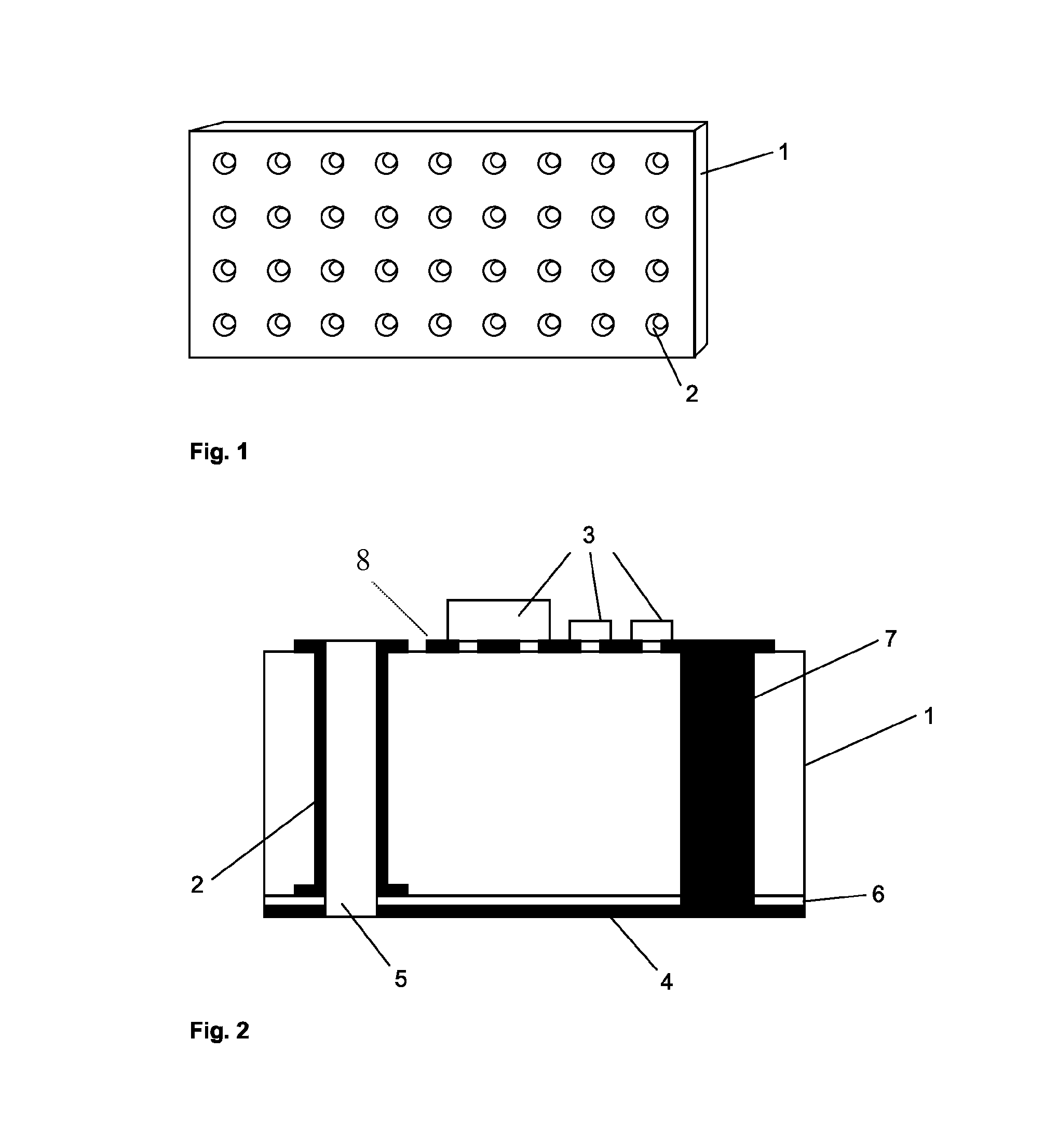
[0030]FIG. 1 shows an overall view of a plasma array according to the invention with 4×9 individual plasma cells, characterized by hollow electrodes 2 formed in a substrate 1.

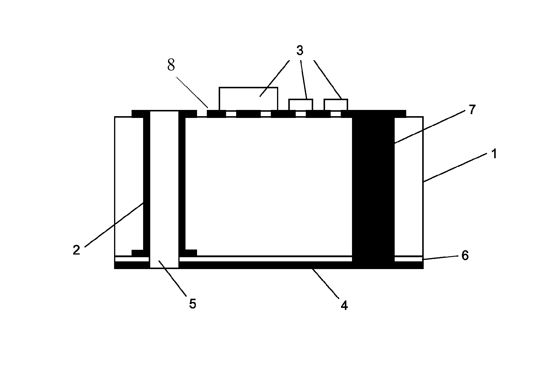
[0031]FIG. 2 shows a cross sectional view of an individual plasma cell. The hollow electrode 2 is formed by a metallic coating of a microhole made in the substrate 1. Formation of the holes and their coating is done with the well-known methods used in semiconductor technology. On the upper side of substrate 1 the hollow electrode 2 is connected with a freely-oscillating oscillator 3, integrated into substrate 1, which is designed, e.g., with a frequency of 5.8 GHz (ISM-frequency). The arrangement of oscillators 3 directly on the substrate 1 makes the array into a fully-independent component that only requires a voltage source. The power of an individual plasma cell can be limited to less than 10 watts so that plasmas can be formed with very small energy input, which also enables good scalability, as well as the...


PUM

PropertyMeasurementUnit
diameteraaaaaaaaaa
frequencyaaaaaaaaaa
voltagesaaaaaaaaaa

Abstract

A microplasma array for the production of low-temperature plasmas at or near atmospheric pressures is described. The walls of holes made in a substrate at regular intervals with respect to one another form hollow electrodes and are coated with metal. The hollow electrodes are supplied individually or as a group from one side of the substrate with an electrical excitation in the GHz-region.

Description

CROSS-REFERENCE TO RELATED APPLICATIONS[0001]This application is a United States nationalization of International Application No. PCT / EP2006 / 050157 filed Jan. 11, 2006, which claims priority to German Application Serial No. 10 2005 002 142.5 filed Jan. 12, 2005, each of which is incorporated herein by reference in its entirety.FIELD OF THE INVENTION[0002]The invention concerns a microplasma array for producing low-temperature plasmas at or near atmospheric pressures.BACKGROUND OF THE INVENTION[0003]Plasmas are used in many sedimentation-, etching-, and layer formation processes.[0004]In plasma reactors that produce a low temperature plasma, either a high frequency voltage of 10 to 30 MHz is applied to two parallel plate electrodes, or microwaves in the GHz region are introduced into a vacuum chamber, in which case more than 500 watts are required.[0005]The most recent attempts involve attempts to produce suitable low-temperature plasmas even under non-vacuum conditions. Such reactor...

Claims


Application Information

Patent Timeline
Patent Type & Authority Patents(United States)
IPC IPC(8): B01J19/08
CPCH01J37/32082H01J37/32596H01J61/09
Inventor GESCHE, ROLAND
Owner FORSCHUNGSVERBUND BERLIN EV
Learn More