Method and device for the infiltration of a structure of a porous material by chemical vapour deposition

a technology of porous materials and infiltration methods, which is applied in the direction of chemical vapor deposition coating, metallic material coating process, special surfaces, etc., can solve the problems of high deposition thickness, difficult control of liquid phase deposition, and inability to uniformly deposition

Active Publication Date: 2013-10-01
COMMISSARIAT A LENERGIE ATOMIQUE ET AUX ENERGIES ALTERNATIVES
View PDF9 Cites 1 Cited by
  • Summary
  • Abstract
  • Description
  • Claims
  • Application Information

AI Technical Summary

Benefits of technology

[0023]The particular geometry of the support provided with openings enables an efficient impregnation of the porous material structure of filtering support for catalysis type such as a foam or honeycomb with porosities from 2 to 600 cpsi (channels per square inch) and / or 2 to 60 ppi (pores per square inch). It leads to a deposition of uniform active layer not only from the point of view of the thickness but also the structure. The impregnation in depth of the filtering walls of such a filtering support favours the exchange in volume and enables the specific surface to be optimised.
[0024]Controlling the operating conditions makes it possible, in addition, to modulate the morphology (size) and the concentration (dispersion) of the catalysts and thus to enable the synthesis of very finely dispersed (inter-particle distance<50 nm) particles of nanometric size (<20 nm).

Problems solved by technology

The main drawbacks of this technique are as follows:It requires a high quantity of deposited material: from 5 to 10 times more than by CVD.It induces a non-uniform deposition due to the flow of liquid within porous structures.It must be followed by a heat treatment step (drying and calcination).
But such a liquid phase deposition is difficult to control and the deposition thickness is high.

Method used


Image

  • Method and device for the infiltration of a structure of a porous material by chemical vapour deposition
  • Method and device for the infiltration of a structure of a porous material by chemical vapour deposition
  • Method and device for the infiltration of a structure of a porous material by chemical vapour deposition

Examples


example of embodiment

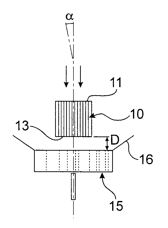
[0057]In one embodiment, the porous material structure 10 is a ceramic structure of honeycomb, ceramic foam type, or any other complex geometric structure.

[0058]This dense or macroporous structure may be made of cordierite (2Al2O3.2SiO2.5MgO), silicon carbide (SiC), titanium alumina (Al2O3.TiO2), zircon alumina (Al2O3.ZrO2), etc.

[0059]The following steps are then carried out:[0060]deposition of a uniform thin film of “washcoat”, which may be composed of Mixed oxides of different nature (Al2O3, CeO2—ZrO2, BaO2, zeolite, TiO2 / V2O5, etc.).[0061]chemical vapour deposition, which consists in dispersing noble or non-noble metals (catalysts) on the “washcoat”, the noble metals being able to be of different nature depending on the targeted type of catalysis (Pt, Pt / Rh, Ag / Pt / Rh, Ag, Au, etc.).

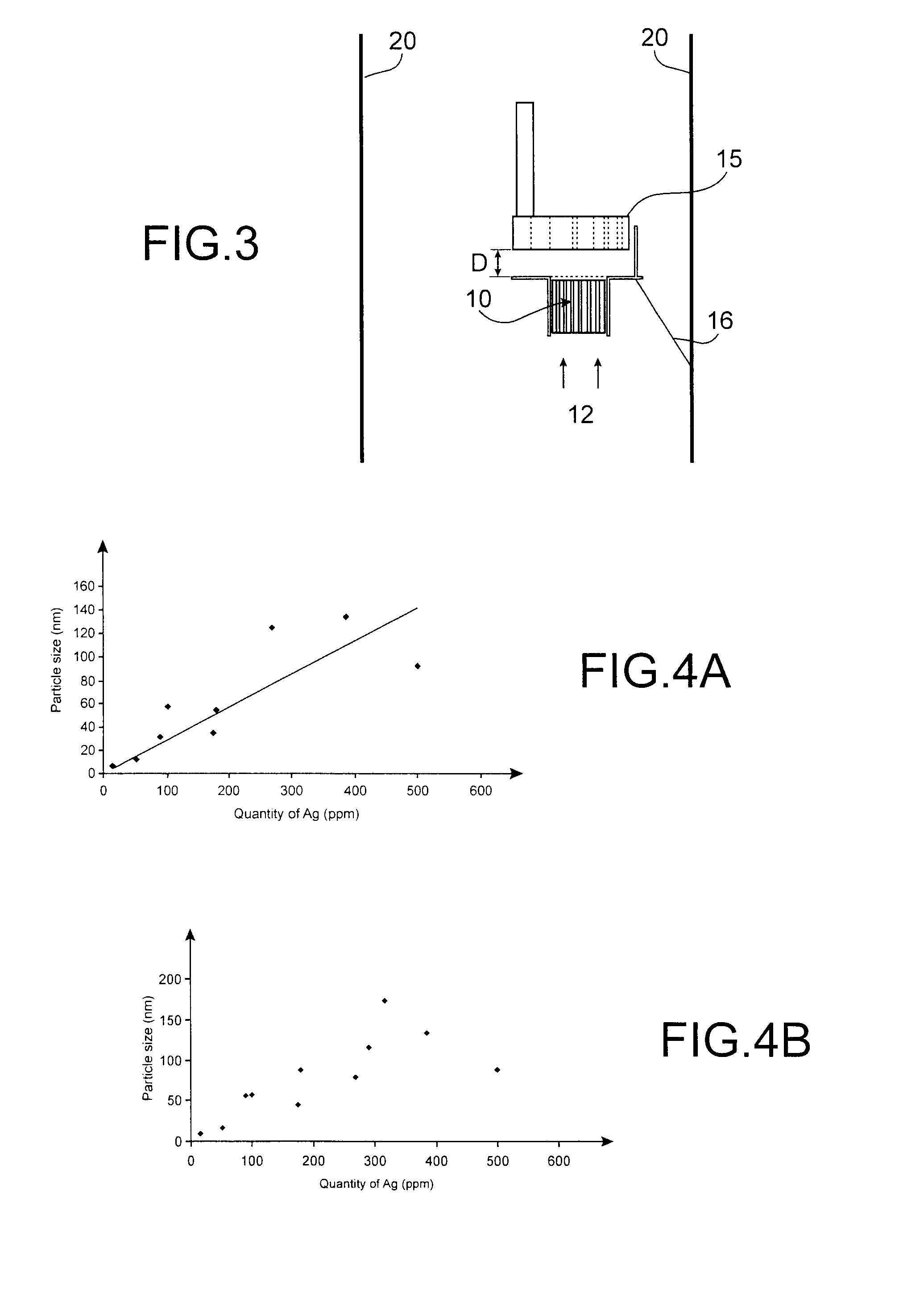
[0062]The size of the particles obtained oscillates between 3 and 200 nm, as illustrated in FIGS. 4A and 4B, as a function of the Ag load rate (content) between 20 and 4000 ppm.

[0063]It is interesting ...


PUM

PropertyMeasurementUnit
angleaaaaaaaaaa
angleaaaaaaaaaa
diameteraaaaaaaaaa

Abstract

A method and a device for infiltration of a structure made of a porous material by chemical vapor deposition. According to the method, a first face of the porous material structure is exposed to a gaseous flow, and the second face is maintained at least partially free from any contact.

Description

TECHNICAL FIELD[0001]The present invention relates to a method and device for the infiltration of a structure made of a porous material by chemical vapour deposition (CVD), to obtain in particular multilayers or heterostructures for catalytic systems (“washcoat”+metal).STATE OF THE PRIOR ART[0002]“Washcoat”+metal type catalytic systems are available in the form of continuous and uniform thin films and / or particles of nanometric size (diameter from 1 to 100 nm) well dispersed on the surface of a dense or porous structure. Their application areas concern, for example, the catalysis of air (treatment of pollutants: volatile organic compounds (VOC), nitrogen oxides (NOx)), generation of hydrogen by reforming of hydrocarbons, or biofuels or the storage of hydrogen by adsorption.[0003]The conventional technique for forming such catalysts is impregnation by liquid process, for example by deposition of silver particles as described in the document referenced [1] at the end of the descriptio...

Claims


Application Information

Patent Timeline
Patent Type & Authority Patents(United States)
IPC IPC(8): C23C16/06
CPCC23C16/045C23C16/458
Inventor DONET, SEBASTIENEMIEUX, FABRICEFILHOL, LIONELTHOLLON, STEPHANIE
Owner COMMISSARIAT A LENERGIE ATOMIQUE ET AUX ENERGIES ALTERNATIVES
Why Eureka
Try Eureka