
Method of manufacturing of lightweight structural trim part and lightweight structural trim part produced

a manufacturing method and technology of lightweight structural trim parts, applied in the direction of roofs, hollow wall parts, instruments, etc., can solve the problems of not contributing to the stiffness of the vehicle structure, hammering the consolidation of these layers, and not being suitable for use as a vehicle's loadfloor, truck walls or other structural trim parts, etc., to achieve enhanced acoustical performance and stiffness, and simple manufacturing method

Active Publication Date: 2013-10-01
AUTONEUM MANAGEMENT AG
View PDF10 Cites 3 Cited by
  • Summary
  • Abstract
  • Description
  • Claims
  • Application Information

AI Technical Summary

Benefits of technology

The present invention provides a simple method for manufacturing a lightweight structural trim part with enhanced acoustical performance and stiffness. This trim part can be used as a vehicle's structural trim part. The method involves a one-step process and does not cause any visible dark-stained spots or holes. The final product has improved sound absorption and stiffness, making it suitable for various structural trim parts in vehicles. The method is easy to run and cost-effective.

Problems solved by technology

Unfortunately the air pressed into the moulding tool is flowing through and cooling down the inner most non-woven layers and thereby hampers the consolidation of these layers.
The body produced by this method is stiff enough to be able to support its own weight, but doesn't contribute to the stiffness of the vehicle's structure and is not suitable to be used as a vehicle's loadfloor, undershields, truck's walls or other structural trim parts.

Method used


Image

  • Method of manufacturing of lightweight structural trim part and lightweight structural trim part produced
  • Method of manufacturing of lightweight structural trim part and lightweight structural trim part produced
  • Method of manufacturing of lightweight structural trim part and lightweight structural trim part produced

Examples


Embodiment Construction

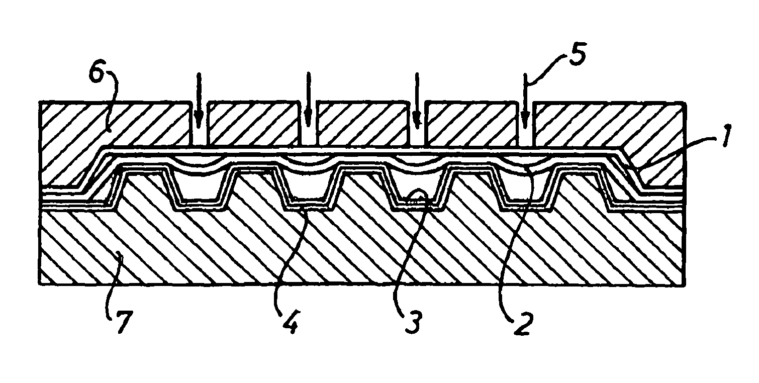
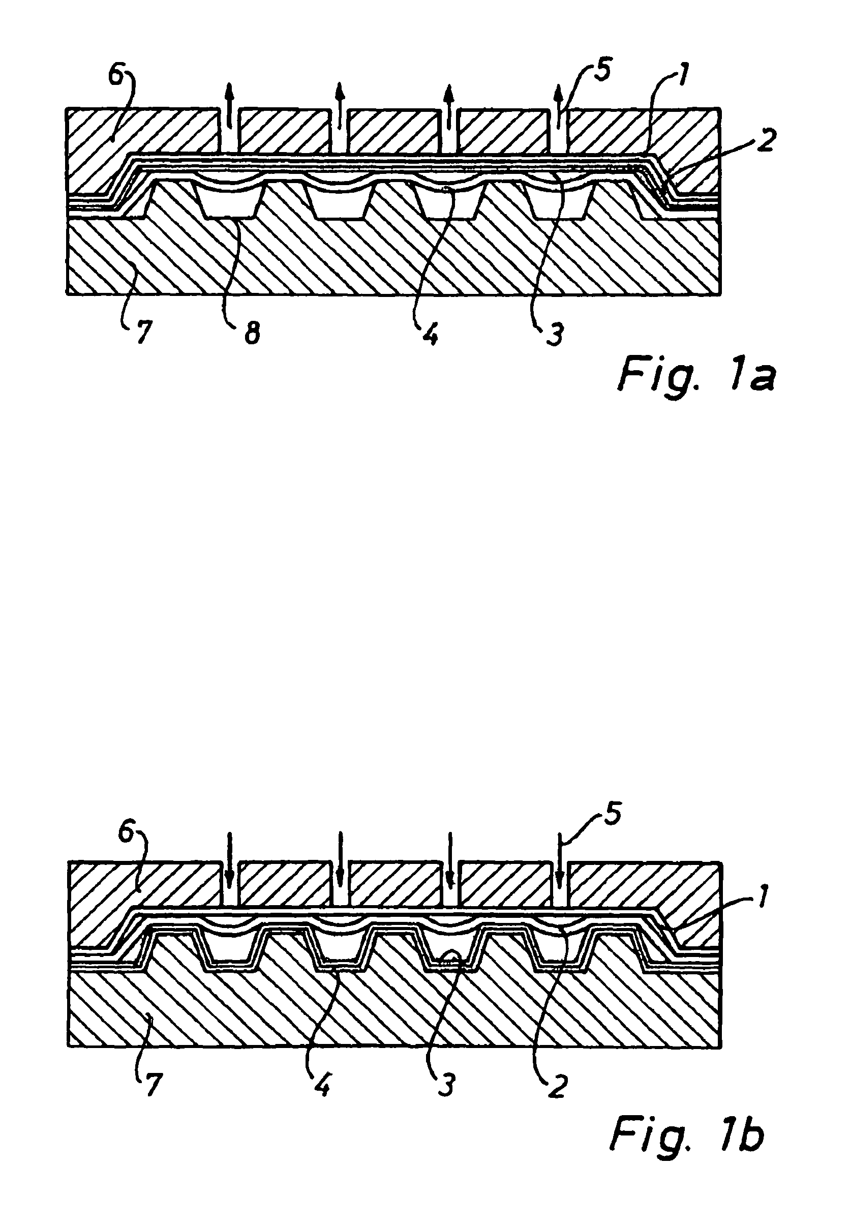
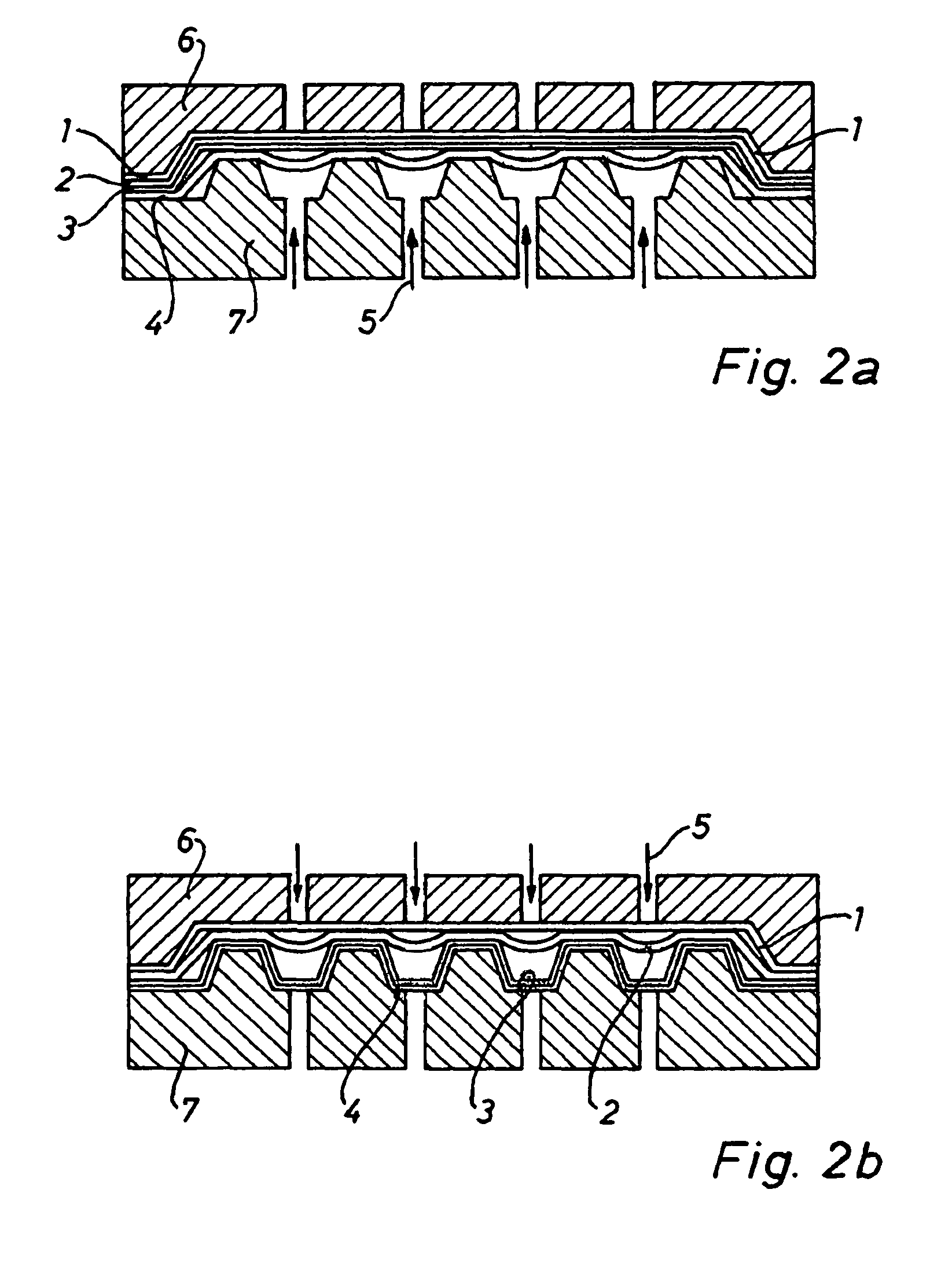
[0023]FIGS. 1a and 1b are concerned with a first process for manufacturing an acoustic body designed as a double skins part. As an example the mould is loaded with four layers, whereby the outer layers consist of a thermoplastic felt. This felt may consist of a PP non-woven comprising 20% to 60% of reinforcing fibres, in particular glass fibres. The weight of these layers may vary between 800 g / m2 to 2000 g / m2 depending on the mechanical specifications and targets given. A first film may consist of 100% PP film of 150 microns of thickness. A second film may consist of a porous non-woven of 100% PET and may have a weight of 40 g / m2. According to the invention the method for manufacturing a lightweight structural trim part comprises the following steps:[0024]inserting a plurality of layers into a moulding tool comprising a first moulding half 6 and a second moulding half 7, which second moulding half comprises a plurality of cup-like indentations 8, and which plurality of layers at le...


PUM

PropertyMeasurementUnit
thicknessaaaaaaaaaa
thicknessaaaaaaaaaa
air permeableaaaaaaaaaa

Abstract

A method for manufacturing a lightweight structural trim part is comprising the following steps: (A) inserting a plurality of layers into a molding tool comprising a first molding half (6) and a second molding half (7). The second molding half (7) comprises a plurality of cup-like indentation (8). The plurality of layers at least comprises a first air permeable skin layer (1) facing the first molding half (6), a second air tight skin layer (3,4) facing the second molding half (7), and a film layer (2) between the two skin layers. (B) Closing the molding tool and discharging gas from one side in order to press the first skin layer against the first molding half. (C) Shaping and consolidating the first porous skin layer. (D) Charging with pressurized air the first space in order to press the second skin layer against the second molding half. (E) Shaping and consolidating the second skin layer. (F) Meanwhile bonding the first and second skin layer to each other in the area between the cup-like indentations, in order to form an acoustic body comprising a plurality of cup-like cavities.

Description

CROSS REFERENCE TO RELATED APPLICATIONS[0001]This application is a National Stage of PCT / EP2006 / 005861 filed Jun. 19, 2006, claiming priority of Application No. EP 05013120.0 filed Jun. 17, 2005, and is incorporated by reference herein in its entirety.BACKGROUND OF THE INVENTION[0002]1. Field of the Invention[0003]Present invention is concerned with a method for manufacturing a lightweight structural trim part and with a lightweight structural trim part manufactured in accordance with this method.[0004]2. Description of the Related Art[0005]Lightweight acoustic bodies and methods to manufacture such bodies are well known in the field of automotive technology. A method to manufacture a sound attenuating rear parcel shelf is known from WO03 / 018291. This method allows to produce a hollow body comprising two thermoformed outer skins, each comprising a porous layer. A sealing film is integrated into each of the two skins. Inner most non-woven insulating sheets are disposed between the se...

Claims


Application Information

Patent Timeline
Patent Type & Authority Patents(United States)
IPC IPC(8): B32B3/26B32B37/10B29C51/10B29D24/00
CPCB29C49/0047B29C51/267B32B3/28B32B5/26B32B27/12B60R13/08G10K11/168Y10T428/24562B29C51/145B29C2791/001B29C2791/006B29C2791/007B29K2023/12B29K2105/04B29K2105/0854B29K2995/0002B29L2009/00B29L2024/00B32B2262/0215B32B2262/0253B32B2307/102B32B2307/544B32B2307/546B32B2307/718B32B2605/00Y10T428/24661B29C49/221B29C2949/3032B29C49/0691
Inventor BUSKA, BERTRANDSIMON, DAVIDAUGER, VIRGINIE
Owner AUTONEUM MANAGEMENT AG
Learn More