
ULT cable support system

a technology of support system and cable, which is applied in the direction of machine support, machine support, shock absorber, etc., can solve the problems of affecting the service life of overhead cables, and prone to destructive forces of overhead cables

Active Publication Date: 2013-10-08
UNDERGROUND DEVICES
View PDF73 Cites 19 Cited by
  • Summary
  • Abstract
  • Description
  • Claims
  • Application Information

AI Technical Summary

Benefits of technology

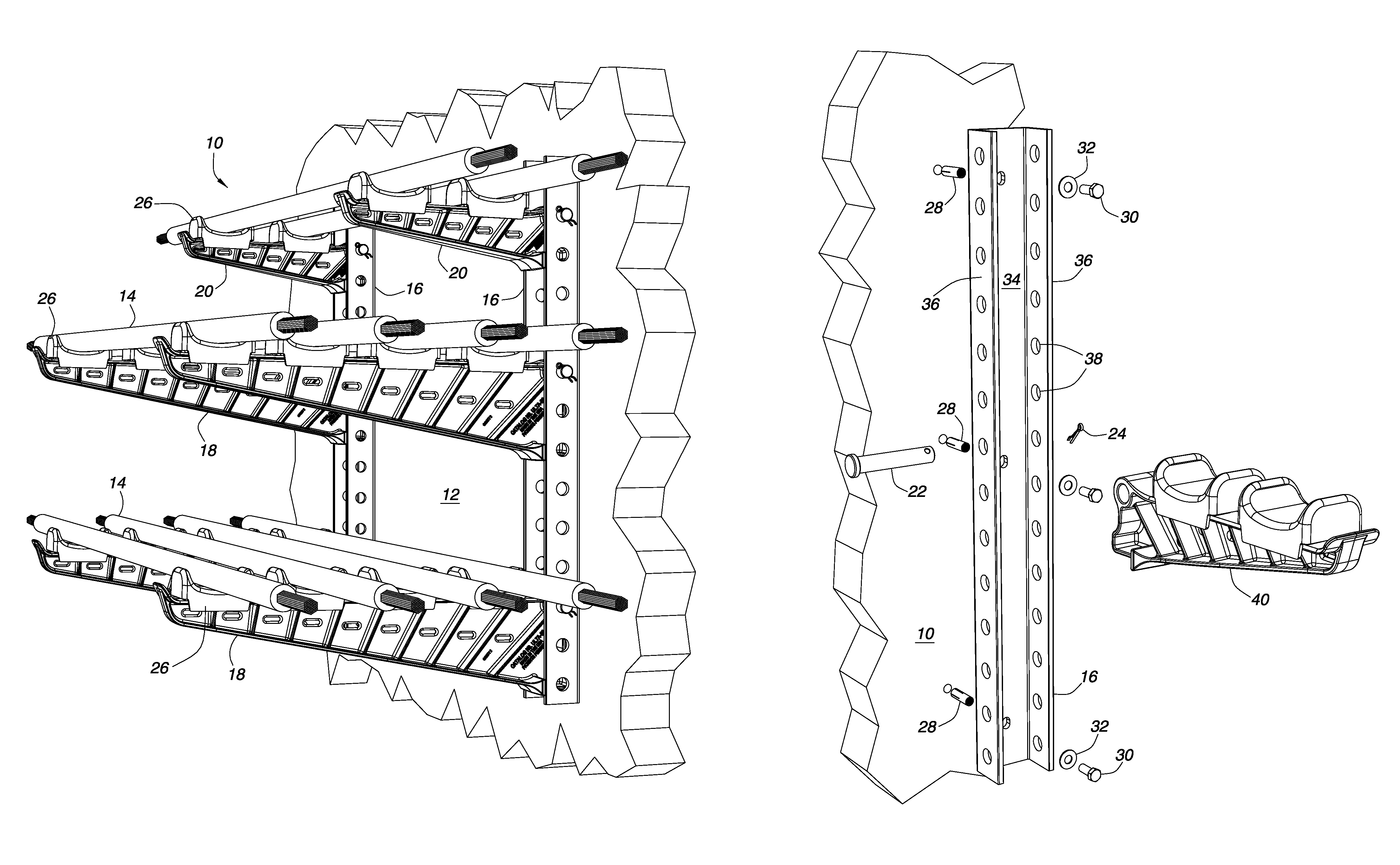
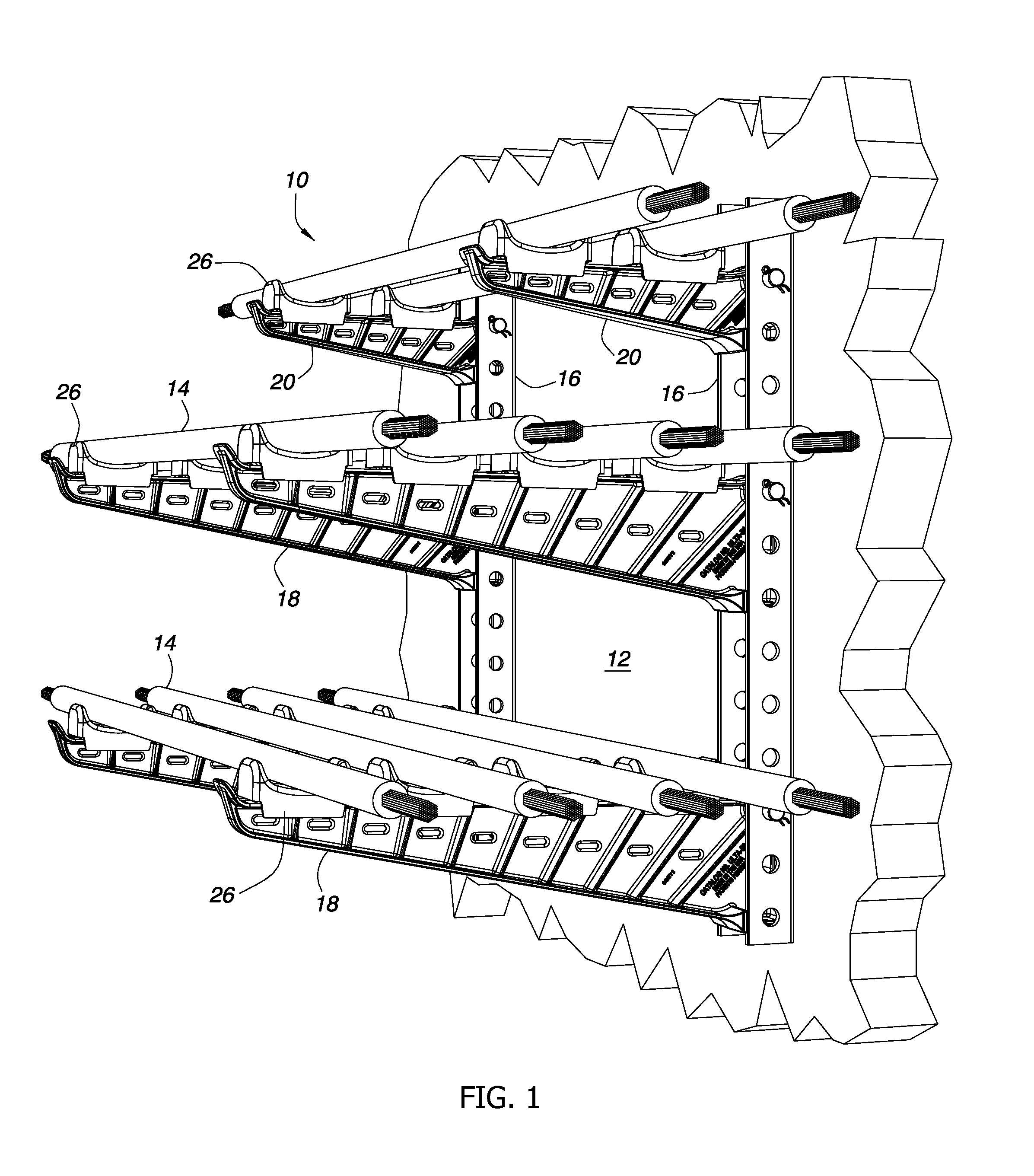
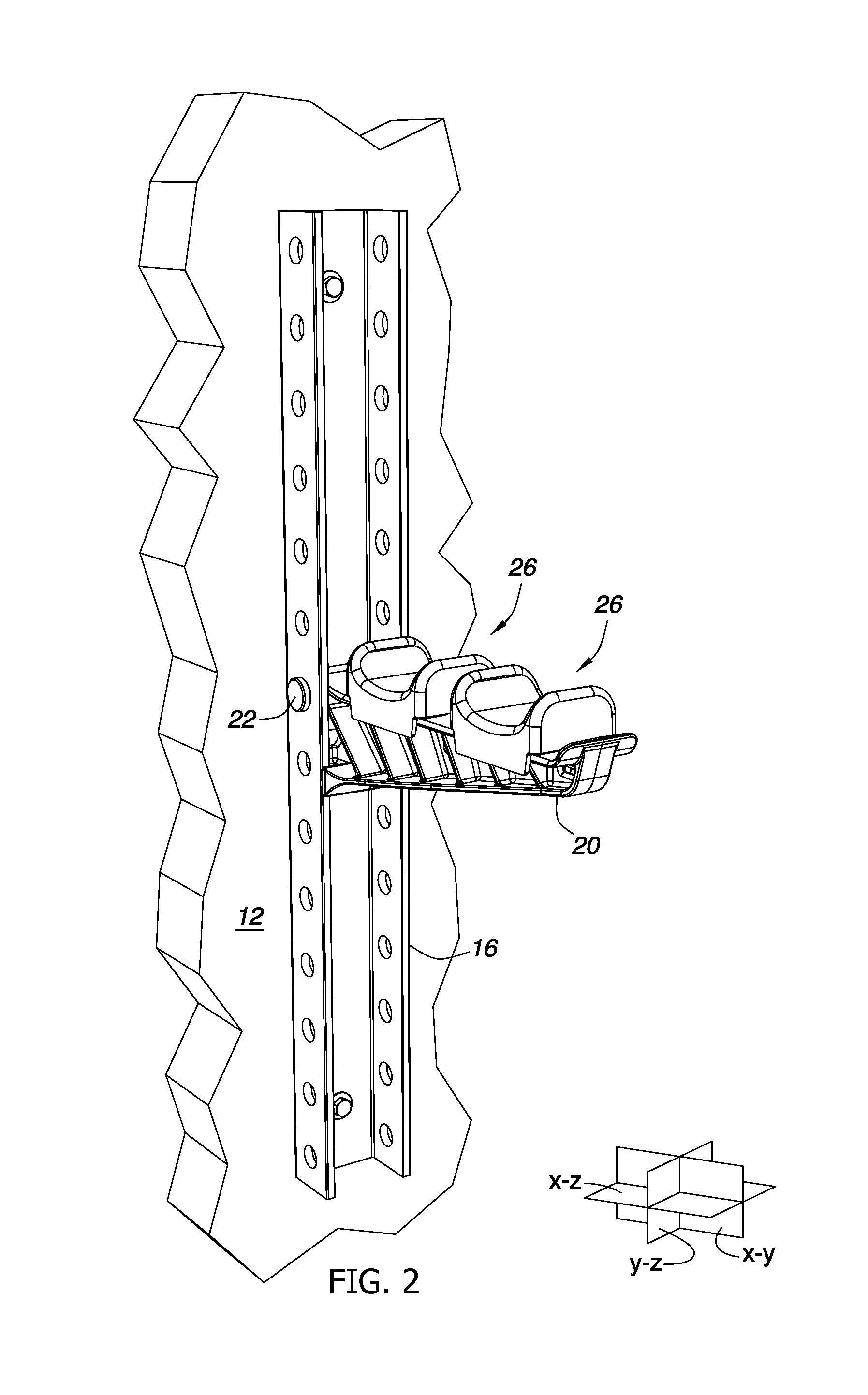
The invention is a cable rack arm that can be easily attached to a stanchion and has a continuous surface for mounting cable loads. The cable rack arm has an upper flanged portion, a lower portion with a gusset for mating with the stanchion, and a web connecting the two portions. It also includes an interface for mounting to the stanchion, a heel, an orifice, and a hollow area between the heel and orifice. The cable rack arm can be used for different cable load requirements and has a simple design for easy installation.

Problems solved by technology

The overhead network includes much redundancy and many checks and balances to keep it reliable, but inherently there are weaknesses.
Overhead cables are prone to the destructive forces of weather.
Storms, high winds, ice, hurricanes, tornadoes, etc., wreak destructive forces that knock down overhead lines and interrupt electrical and telephone service.
In many places, overhead cables are not desirable, such as over waterways, at and near airports or over major highways, just to name a few.
Overhead cables are unsightly.
The environment in underground power and communications manholes is indeed harsh.
Manholes may fill with water that is often contaminated with sewage, fertilizer runoff, tree roots, and chemicals, including caustic materials.
Others fill periodically but are hot and have extremely high humidity, while still others fill and empty with ocean tides.
The water level in manholes located close to the ocean often changes with the tide, and the constantly-changing interface only increases the likelihood for corrosion.
The condition of water in underground power and communications manholes occasionally is fresh and clean but most often is contaminated, as noted above, or is salt water, both of which can be very corrosive and also conductive.
The walls, such as concrete walls or other structures, will also be in intimate contact with the racks, adding their chemical potential for corrosion to the racks.
All these stresses combine to make the underground a challenging environment for cable racks.
Eventually, the galvanized coating is consumed and the steel racks may oxidize or corrode away, leaving the power and communications cables without support.
Two phenomena, galvanic corrosion and stray current corrosion, occur in flooded underground manholes to cause this deterioration.
Galvanized steel cable supports are very vulnerable to both galvanic and stray current corrosion and often become severely corroded to a point that they will no longer support the cables in a very short period of time.
Cathodic parts in the manhole, parts made from more noble metals such as stainless steel, may be damaged in the galvanic corrosion process due to generation of electrolytic hydrogen on their surfaces causing hydrogen embrittlement.
Stray current corrosion of underground power and communication cable supports is usually caused by power and communications manholes being located in the vicinity of electric rail tracks, pipe lines that are cathodicly protected or the like.
Underground galvanized steel cable supports that are severely corroded and can no longer support the cables result in power and communications interruptions and a safety hazard to technicians who enter the manhole.
Another safety issue is that galvanized steel cable supports are conductive.
If a technician inadvertently touches the energized cable support he may be electrocuted.
The shock and vibration are generated by heavy vehicular traffic in the roadways over and near manholes.

Method used


Image

  • ULT cable support system
  • ULT cable support system
  • ULT cable support system

Examples


Embodiment Construction

[0039]Embodiments of the cable arms and saddles described herein are preferably molded from plastic materials. In this context, “plastic” materials include any resinous, thermoset, or thermoplastic materials, including materials that are reinforced or otherwise altered, and which are formed by molding. Thus, in one embodiment, nylon with short or long glass fibers is used to make strong, stiff, and environmentally-resistant rack arms. In the present context, short glass fibers intends glass fibers from about ⅛″ (about 3 mm) long to about ¼″ (about 6 mm) long. Long glass fibers, from about 3 / 16″ (about 5 mm) to about ⅜″ (about 10 mm) or longer, may be used instead for greater strength and stiffness. Glass fibers with diameters from about 0.009 mm (0.00035 in) to about 0.011 mm (0.00043 in) may be used for reinforcement. Fibers with other diameters may also be used.

[0040]In one embodiment, cable rack arms as described below may be compression-molded with 50% long glass fibers. Other p...


PUM


Abstract

A cable rack arm and support system suitable for underground power and communication service is made from reinforced non-metallic polymers that will not rust or corrode. A cable rack arm up to thirty inches long may be compression molded with long glass fibers in a polyester or vinylester matrix. Each cable rack arm is securely mounted to a non-metallic stanchion that may be made from a reinforced, pultruded composite material. Nonmetallic pins may be used to secure the cable rack arms to the stanchions. Each cable rack arm then supports one or more cables in cable saddles that are snap-fit atop the arm, thus keeping the cables accessibly organized in a manhole, tunnel or vault. Each saddle may include elastomeric dampening material to reduce shock and vibration in the mechanical and electrical environment in underground tunnels, vaults and manholes.

Description

TECHNICAL FIELD[0001]The technical field of the invention is that of racks for supporting power and communication cables in underground manholes, vaults, and tunnels.BACKGROUND[0002]This disclosure begins with a brief discussion of why manholes, vaults and tunnels exist. In the modern world of the twenty-first century, we require electricity and communications for all aspects of industry and for our daily lives. Without them, our existence would be just as it was before the Industrial Revolution. All electricity not generated on site, as with local generators and solar panels, is transmitted and distributed through copper and aluminum cables. All communications that extend beyond the distance a person's voice can carry are transmitted at some point, and for the most part, through copper conductive cables or glass fiber cables. There are billions of miles of cables extending to almost every place and every point on planet Earth.[0003]Our dependence on electricity and communications d...

Claims


Application Information

Patent Timeline
IPC IPC(8): A47F7/00
CPCH02G3/30F16F7/14F16L3/16F16L3/221
Inventor MCCOY, DONALD P.
Owner UNDERGROUND DEVICES
Learn More