Reduced water mist generating device and electric apparatus

a technology of generating device and water mist, which is applied in the direction of free-cooling system, combustion air/fuel air treatment, curling-tongs, etc., can solve the problems of long time-consuming storage of food items, and achieve the effect of reducing skin inflammation, lubricating skin, and inhibiting skin aging

Inactive Publication Date: 2013-10-15
PANASONIC CORP
View PDF41 Cites 6 Cited by
  • Summary
  • Abstract
  • Description
  • Claims
  • Application Information

AI Technical Summary

Benefits of technology

[0006]It is an object of the present invention to resolve the abovementioned problem and provide a reduced water mist generating device that can generate and atomize reduced water and supply the atomized reduced water as a reduced water mist, and also to provide an electric apparatus equipped with the reduced water generating device.
[0009]Therefore, it is possible to generate and atomize the reduced water and provide the atomized reduced water as a reduced water mist. As a result, aging of the human skin can be inhibited, skin can be lubricated, and skin inflammation can be reduced. In addition, storage objects such as food can be stored for a long time.

Problems solved by technology

In addition, storage objects such as food can be stored for a long time.

Method used


Image

  • Reduced water mist generating device and electric apparatus
  • Reduced water mist generating device and electric apparatus
  • Reduced water mist generating device and electric apparatus

Examples


configuration example 1

SPECIFIC CONFIGURATION EXAMPLE 1

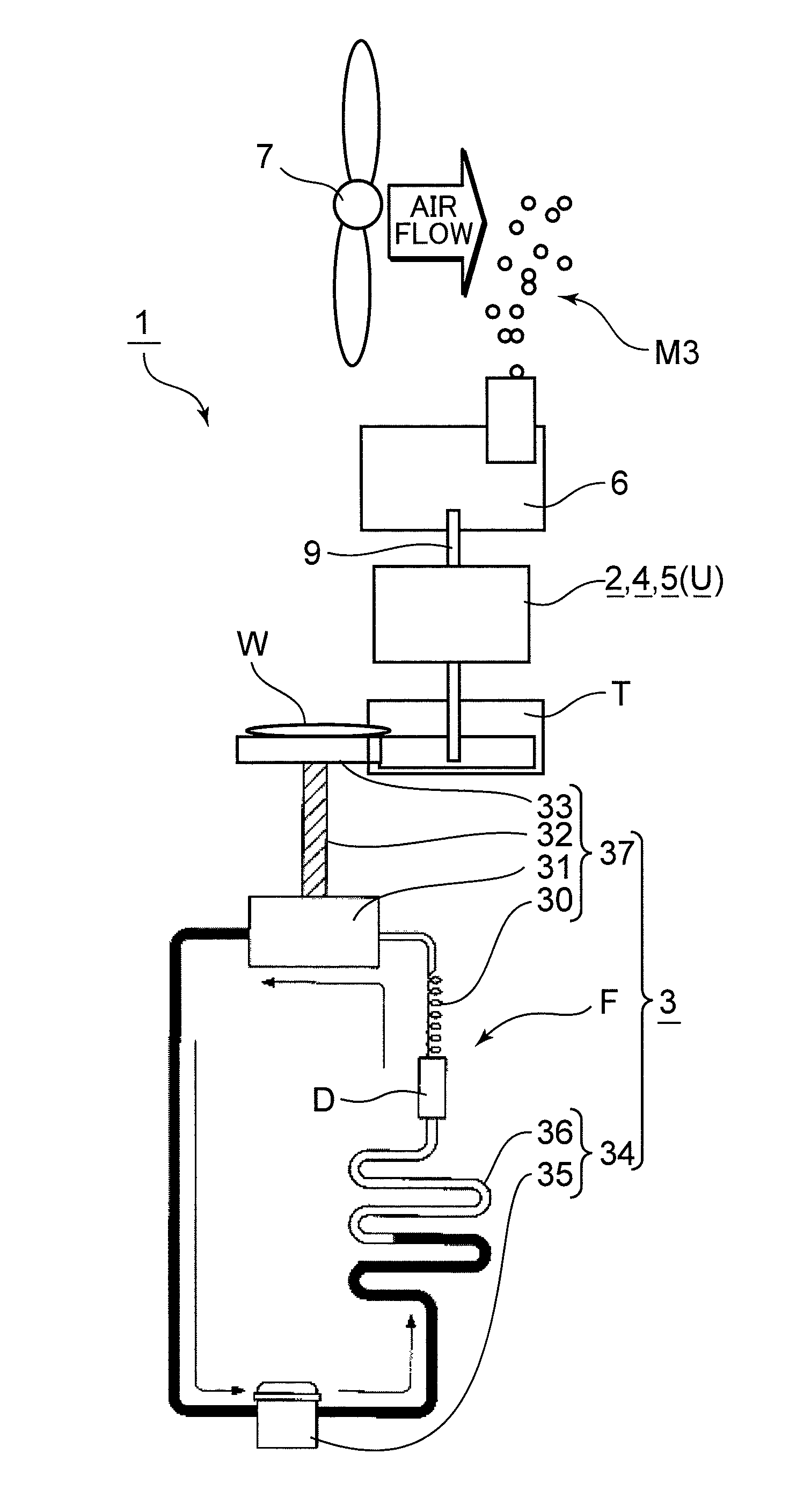
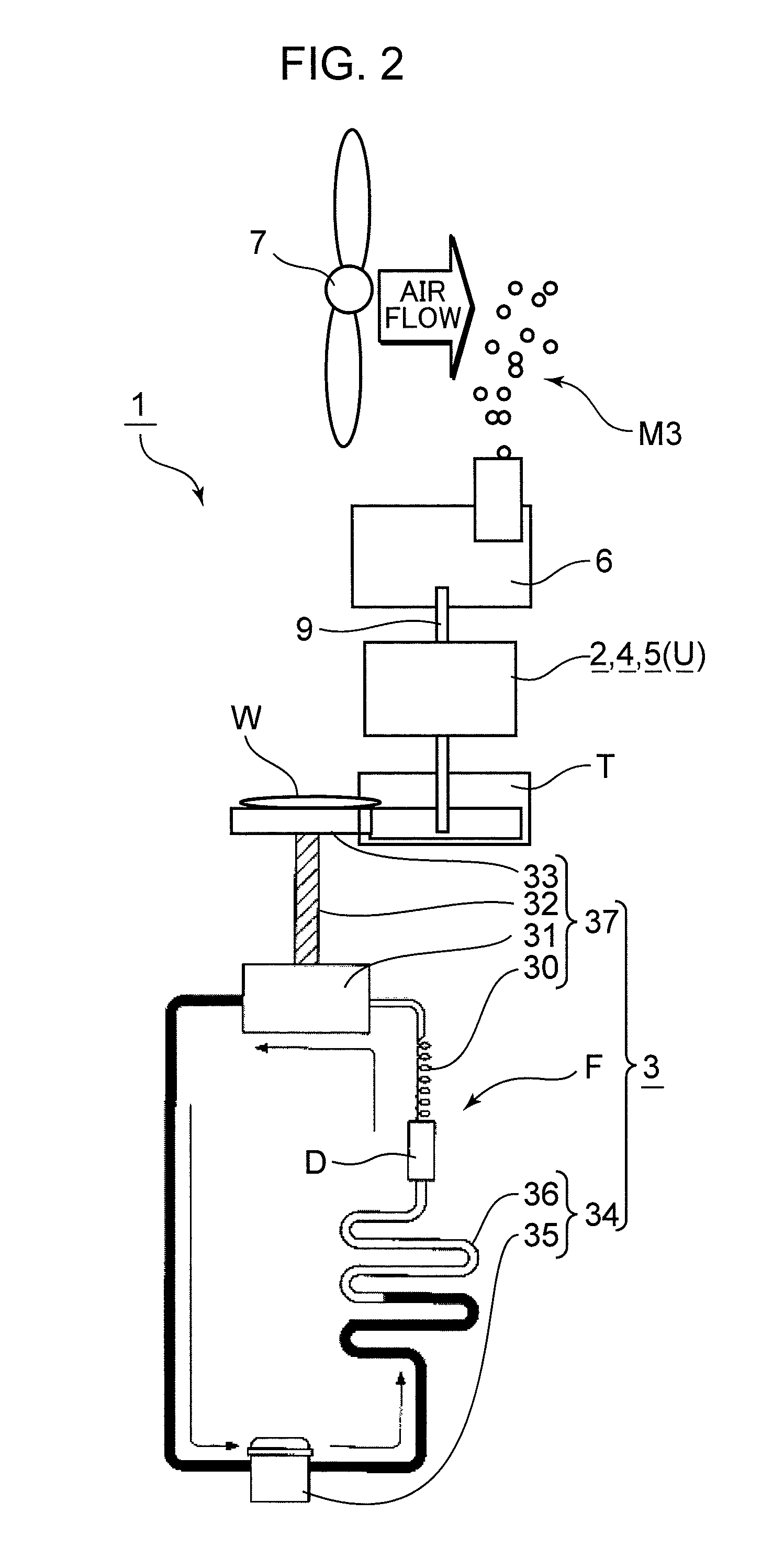
[0048]In the reduced water mist generating device 1 shown in FIG. 2, the water acquiring section 3 includes a heat radiating section 34 that compresses refrigerant gas to a high-temperature and high-pressure state and then causes heat radiation to obtain refrigerant liquid, and a cooling section 37 that depressurizes the refrigerant liquid and then evaporates the refrigerant liquid to obtain refrigerant gas. Thus, the water acquiring section 3 includes a heat exchanger having the heat radiating section 34 and the cooling section 37.

[0049]In such water acquiring section 3, the heat radiating section 34 and the cooling section 37 are provided in a refrigeration cycle section F. The heat radiating section 34 is provided with a compressor 35 that compresses the refrigerant gas to a high-temperature and high-pressure state and a condenser 36 in which the refrigerant gas at a high temperature and under a high pressure is cooled by heat radiation and refrige...

configuration example 2

SPECIFIC CONFIGURATION EXAMPLE 2

[0055]In the reduced water mist generating device 1 shown in FIG. 3, the water acquiring section 3 includes a Peltier element 38 that acquires water by condensation of moisture contained in the air through cooling with a cooling surface 40.

[0056]The Peltier element 38 has the cooling surface 40 and a heat radiating surface 42. The dew condensation water generating section 33 is attached to the cooling surface 40. The cooling surface 40 and the dew condensation water generating section 33 may be thermally connected. A heat radiating fin 43 is attached to the heat radiating surface 42.

[0057]In such water acquiring section 3, when an electric current is supplied to the Peltier element 38 by a power source 41 for the Peltier element, the cooling surface 40 of the Peltier element 38 is cooled and this cooling effect reaches the dew condensation water generating section 33. As a result, the dew condensation water generating section 33 is also cooled, the ai...

configuration example 3

SPECIFIC CONFIGURATION EXAMPLE 3

[0061]In the reduced water mist generating device 1 shown in FIG. 4, the water acquiring section 3 includes an adsorbent 45 that adsorbs moisture contained in the air and a heater 49 that heats the adsorbent 45 and causes desorption of the moisture adsorbed by the adsorbent 45. In this case, the preferred adsorbent 45 is a zeolite.

[0062]In such water acquiring section 3, the water tank T from a hard material such as polypropylene is provided in the lower portion inside a housing 51, and an upper opening Ta of the water tank T is closed with an adsorbing body 44.

[0063]The adsorbing body 44 is constituted by the adsorbent 45 as the main component thereof, a water-permeable hard rear plate 46 such as a mesh provided on the rear surface side of the adsorbent 45, and a moisture-permeable and water-impermeable film 47 provided on the front surface side of the adsorbent 45. The rear plate 46 is supported by a receiving section 48 provided in the upper openin...


PUM

PropertyMeasurementUnit
temperatureaaaaaaaaaa
pressureaaaaaaaaaa
insulatingaaaaaaaaaa

Abstract

A reduced water mist generating device (1) is provided with a water acquiring section (3) that acquires water for generating reduced water, a reduced water generating unit (U) that generates the reduced water from the acquired water, a reduced water atomizing section (6) that atomizes the generated reduced water, and a spraying section (7) that sprays the atomized water. With such a configuration, the reduced water can be generated from water, drifted in the form of a mist in a space, and caused to arrive at an object.

Description

TECHNICAL FIELD[0001]The present invention relates to a reduced water mist generating device and an electric apparatus.BACKGROUND ART[0002]Reduced water (for example, hydrogen water or aqueous solution of ascorbic acid) with a reduced component (for example, hydrogen molecules or ascorbic acid) dissolved therein has been used for preventing aging of skin and hair and long-term storage of food.[0003]Patent Document 1 suggests a hydrogen water supply device that can produce reduced water. In the hydrogen water supply device of such kind, part of water that should be supplied into a dwelling is introduced into an electrolysis tank installed outdoors and made containing hydrogen gas and oxygen gas. The water containing hydrogen gas and oxygen gas is then supplied into the dwelling in the form of a mixture with the water that should be supplied into the dwelling.[0004]Thus, in the hydrogen water supply device described in Patent Document 1, water containing hydrogen gas and oxygen gas is...

Claims


Application Information

Patent Timeline
Patent Type & Authority Patents(United States)
IPC IPC(8): B01F3/04
CPCA01N3/00A23B7/015A23B7/148A23L3/30A23L3/3418A45D1/04A45D2/001A45D19/16A61H33/12A61K8/046A61K8/965C02F1/4618F24F6/12F24F6/14B05B5/0255B05B5/057A45D2001/008A61H2033/068A61K2800/87C02F1/70F24F2006/125Y02B30/545Y02E60/366Y02B30/80Y02B30/54Y02B30/70Y02E60/36
Inventor YAMAGUCHI, TOMOHIROOHE, JUNPEIMISHIMA, YUKIKOSUDA, HIROSHIASANO, YUKIYASUKOMURA, YASUHIROSAINOMOTO, YOSHINORI
Owner PANASONIC CORP
Why Eureka
Try Eureka