Tunable colour LED module

a light-emitting diode and led module technology, applied in the direction of lighting and heating apparatus, process and machine control, instruments, etc., can solve the problems of poor colour rendering index, similar lifetime degradation problems, and are typically very difficult to monitor, and achieve uniform chromaticity properties, long and controlled lifetime, and low cost

Inactive Publication Date: 2013-10-15
PHOTONSTAR LED
View PDF20 Cites 67 Cited by
  • Summary
  • Abstract
  • Description
  • Claims
  • Application Information

AI Technical Summary

Benefits of technology

[0024]It is an object of the present invention that tight control of the correlated colour temperature (CCT) and Colour Rendering Index (CRI) of the total emitted light during manufacture is not required. It is a further object of the present invention that the CCT and CRI of the total emitted light is defined using a control system post manufacture rather than by inspection and sorting of the LED module into different CCT bins during module manufacture.
[0030]In preferred embodiments of the present invention, the first and the second reflector cup enables the total emitted light to be more collimated than a Lambertian source and to allow the light emitted from the first and second reflector cup to mix in the far field.
[0076]As will be appreciated by those skilled in the art, the present invention provides the benefits of a low cost LED module with uniform chromaticity properties in the far field and having long and controlled lifetime yet also offer the flexibility and intelligence of tunable colour chromaticity, CRI and intensity either at manufacture or in the end user lighting application. As indicated above, the invention can be implemented in a wide range of configurations and various embellishments of the invention are possible, many of which are described below with reference to the drawings.

Problems solved by technology

However, due to manufacturing inaccuracies associated with variation in LED emission wavelength, LED emission bandwidth, variation in WCE % weight and WCE composition different LED modules will exhibit white light emission characteristics with different chromaticity values.
This is undesirable as sorting and binning of LED modules post manufacture is required.
Firstly, the LED lighting system proposed in U.S. Pat. No. 6,788,011 suffers from poor Colour Rendering Index (CRI) typically around 27-30 because of the individual narrow Red, Green and Blue wavelengths (approximately 10-25 nm bandwidth wavelength emission) having poor representation of the complete visible spectrum of light which is typically experienced from incandescent bulb illumination or blackbody radiation, 120, as shown in the insert in FIG. 1a. As a reference the CRI for a blackbody radiation is 100 and the value ranging between 0 and 100 defines how accurately light will portray colours relative to a blackbody source at the same nominal colour temperature.
Secondly, due to the different LED semiconductor material systems required to generate Red (typically InGaAlP) and Blue or Green (InGaAlN) wavelengths the voltages, lifetime and junction temperature may dramatically vary from one LED to another adversely affecting the stability of the LED lighting system and the overall colour chromaticity with lifetime as well as light intensity. This is typically very difficult to monitor without the addition of feedback control systems.
Additionally, similar lifetime degradation problems compared to LED lighting devices in U.S. Pat. No. 6,788,011 are also experienced with the second semiconductor degrading at a different rate to the first LED.
The white light generated from the LED module suffers from a poor CRI (expected to be approximately 50-60) due to the narrow light emissions in the Blue and Green wavelength regions.
The attenuated green light dramatically affects the total efficiency of the LED module.

Method used


Image

  • Tunable colour LED module
  • Tunable colour LED module
  • Tunable colour LED module

Examples


Embodiment Construction

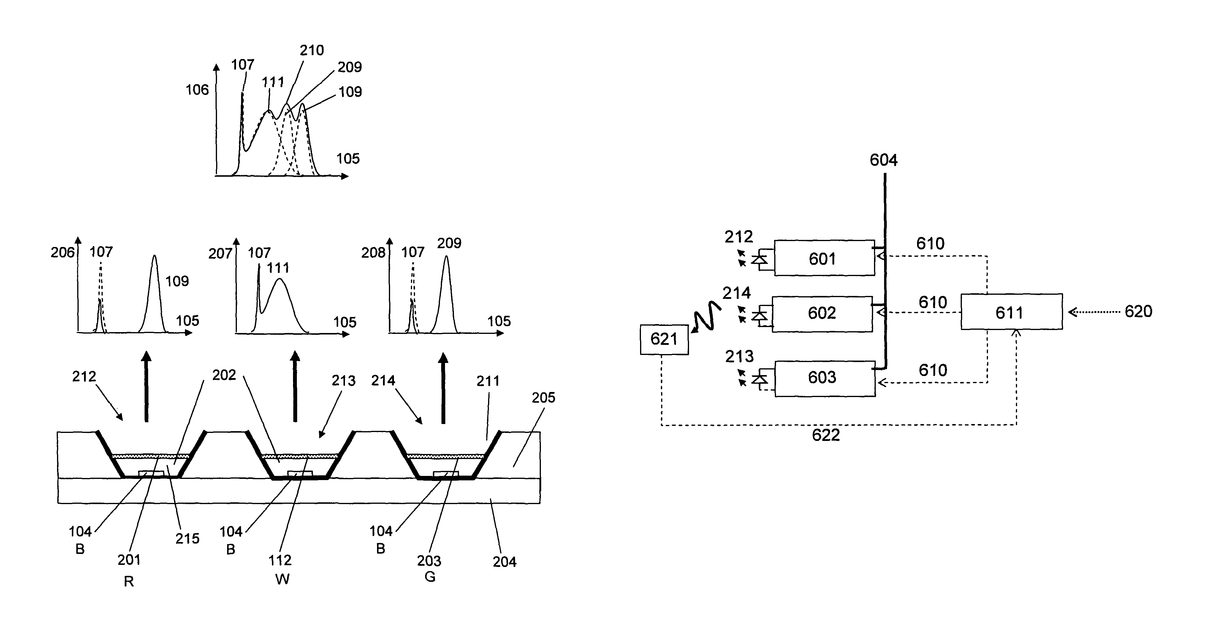
[0094]The object of the present invention is to provide a high wall plug efficiency low cost, low thermal resistance LED chip on board (COB) module and control system having a light output that is flexible and intelligent capable of tuning colour chromaticity, CRI and intensity. The tunability is defined by the control system and may be pre-set during manufacture or actively defined or monitored in the end user lighting application.

[0095]The present invention can be incorporated using a light emitting device (LED) of any semiconductor material system such as, but not restricted to, InGaN, InGaP, InGaAs, InP, or ZnO. However, for illustrative purposes and as a preferred example, Blue wavelength InGaN semiconductor LED having a vertical contact pad structure (sometimes termed vertical LED structure, or thin GaN) will be described in the bulk of the detailed description of the invention.

[0096]In the first aspect of the present invention an LED COB module is devised, as shown in FIG. 2a...


PUM


Abstract

A tunable color LED module comprises at least two sub-modules, each comprising an LED (104), a wavelength converting element (WCE) (201, 112, 203) and a reflector cup. The total light emitted by the module comprises light generated from each LED and WCE and the module is configured to emit a total light having a predefined color chromaticity when activation properties of the LEDs are managed appropriately. The total light may have a broad white emission spectrum (106). The module combines the benefits of a low cost with uniform chromaticity properties in the far field, and offers long and controlled lifetime at the same time as flexibility and intelligence of tunable color chromaticity, Color Rendering Index (CRI) and intensity, either at manufacture or in an end user lighting application. A controlled LED module system comprises a control system for the managing activation properties of the LEDs in the sub-modules. Also described is a method of manufacture.

Description

[0001]This application is a national phase of International Application No. PCT / GB2009 / 001865 filed Jul. 30, 2009, and published in the English language as WO 2010 / 012999 on Feb. 4, 2010.FIELD OF THE INVENTION[0002]The present invention relates to a colour tunable light emitting diode (LED) module comprising multiple LED die and wavelength converting elements, and in particular a method and device that eliminates manufacturer colour temperature binning by means of a designed colour mix trimming system.BACKGROUND TO THE INVENTION[0003]Light emitting devices and diodes are based on a forward biased p-n junction. LEDs have recently reached high brightness levels that have allowed them to enter into new solid state lighting applications as well as replacements for high brightness light sources such as light engines for projectors and automotive car headlights. These markets have also been enabled by the economical gains achieved through the high efficiencies of LEDs, as well as reliabil...

Claims


Application Information

Patent Timeline
Patent Type & Authority Patents(United States)
IPC IPC(8): F21V9/16H05B44/00
CPCF21K9/00H01L33/50H05B33/0857H05B33/0869H05B33/0872H01L33/005H01L25/0753H01L2924/0002H01L2924/00H05B45/22H05B45/20H05B45/28F21K99/00H01L33/60H05B45/00
Inventor MCKENZIE, JAMES STUARTZOOROB, MAJDLEE, THOMAS DAVID MATTHEW
Owner PHOTONSTAR LED
Why Eureka
Try Eureka