Unlock instant, AI-driven research and patent intelligence for your innovation.

Plasma jet ignition plug

a technology of plasma jet and ignition plug, which is applied in the direction of spark plugs, machines/engines, mechanical equipment, etc., can solve the problems of affecting the durability of plasma jet ignition plugs, affecting the combustion efficiency of combustion chambers, so as to achieve high plasma generation efficiency, prevent the cooling of the center electrode associated with the introduction of new air-fuel mixture into combustion chambers, and prevent the effect of increasing the temperature of the insulator

Inactive Publication Date: 2013-10-15
NGK SPARK PLUG CO LTD
View PDF12 Cites 0 Cited by
  • Summary
  • Abstract
  • Description
  • Claims
  • Application Information

AI Technical Summary

Benefits of technology

The present invention provides a plasma jet ignition plug that exhibits high plasma generation efficiency while restraining the occurrence of preignition. The design of the plug prevents heat transfer to the center electrode and insulator, which reduces the temperature of the front end portion of the insulator and increases the temperature of the center electrode. The plug also has a contact portion that releases heat from the front end portion of the insulator and prevents an increase in temperature of the insulator caused by combustion gas. The plug design satisfies a relational expression and prevents the occurrence of preignition.

Problems solved by technology

Supply of high-energy current causes intensive erosion of the center and ground electrodes and a like problem, potentially resulting in deterioration in durability of the plasma jet ignition plug.
However, an increase in the temperature of the insulator may involve the occurrence of preignition, a phenomenon that ignition takes place in advance of regular ignition timing with the insulator serving as a heat source.

Method used


Image

  • Plasma jet ignition plug
  • Plasma jet ignition plug
  • Plasma jet ignition plug

Examples


examples

Evaluation of Plasma Generation Efficiency

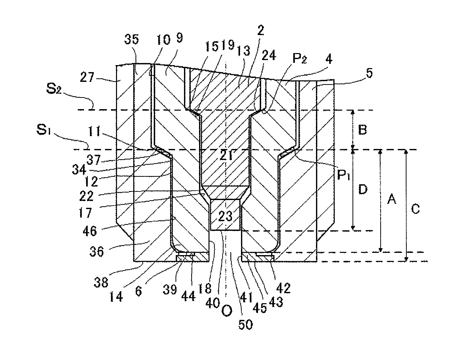
[0057]A plasma generation efficiency evaluation test was conducted on plasma jet ignition plugs which differed in the axial distance A, the axial distance B, and the inside diameter of a front end portion of the axial bore of the insulator (cavity diameter).

[0058]For use in the evaluation test as test samples, the plasma jet ignition plugs similar to the plasma jet ignition plug shown in FIG. 1 were manufactured under the following conditions: the difference (A−D) between the axial distance A and the axial distance D is 1 mm; the disk-like ground electrode having a thickness (C−A) of 0.5 mm and having, at its center, an opening of the same diameter as the cavity diameter is joined to the inner circumferential surface of a front end portion of the metallic shell; and the facing surface of the ground electrode which faces the front end surface of the insulator is in contact with the front end surface of the insulator continuously around the ax...


PUM


Abstract

A plasma jet ignition plug exhibiting high plasma generation efficiency while restraining occurrence of preignition. P1 represents the position of a rear end of a region of a metallic shell ledge, the region being in contact with an insulator. P2 represents the position of a rear end of a region of the insulator ledge, the region being in contact with the center electrode. Front end surfaces of the metallic shell, the insulator, and center electrode, an imaginary plane S1 which is perpendicular to the axis and contains position P1, and an imaginary plane perpendicular to the axis and contains position P2 are disposed in this order from front side to rear side along the axis. The axial distance A from the front end surface of the insulator to imaginary plane S1 and axial distance B from the imaginary plane S1 to imaginary plane S2 satisfy 0.5×A≦B.

Description

FIELD OF INVENTION[0001]The present invention relates to a plasma jet ignition plug.BACKGROUND OF THE INVENTION[0002]Conventionally, a spark plug has been used to ignite an air-fuel mixture through spark discharge (may be referred to merely as “discharge”) for operation of an engine, such as an automotive internal combustion engine. In recent years, high output and low fuel consumption have been required of internal combustion engines. To fulfill such requirements, development of a plasma jet ignition plug has been conducted, since the plasma jet ignition plug provides quick propagation of combustion and exhibits such high ignition performance as to be capable of reliably igniting even a lean air-fuel mixture having a higher ignition-limit air-fuel ratio.[0003]The plasma jet ignition plug has a structure in which an insulator formed from ceramic or the like surrounds a spark discharge gap between a center electrode and a ground electrode, thereby forming a small-volume discharge spa...

Claims


Application Information

Patent Timeline
Patent Type & Authority Patents(United States)
IPC IPC(8): H01T13/20
CPCH01T13/50H01T13/16
Inventor KAMEDA, HIROYUKI
Owner NGK SPARK PLUG CO LTD
Features
  • R&D
  • Intellectual Property
  • Life Sciences
  • Materials
  • Tech Scout
  • Unparalleled Data Quality
  • Higher Quality Content
  • 60% Fewer Hallucinations
Learn More