Ink jet print head and method of manufacturing ink jet print head

a technology of ink jet printing and print head, which is applied in the direction of recording equipment, recording information storage, instruments, etc., can solve the problems of high productivity, complicated entire process, and formation that requires a longer time, and achieve the effect of stable substra

Inactive Publication Date: 2013-10-22
CANON KK
View PDF20 Cites 0 Cited by
  • Summary
  • Abstract
  • Description
  • Claims
  • Application Information

AI Technical Summary

Benefits of technology

[0025]The ink jet print head in accordance with the present invention enables the liquid channel to be formed along the insulating layer. This enables accurate manufacturing of the communication portion between the supply port and the liquid channel, enabling a stable substrate to be provided. Furthermore, the ink jet print head which has the liquid channel shape meeting the intended purpose can be obtained.

Problems solved by technology

This results in film boiling to generate bubbles, so that the pressure of the bubbles causes the ink to be ejected from the corresponding ejection port.
This in turn complicates the entire process.
In this case, the groove formation requires a longer time, which may not result in high productivity.

Method used


Image

  • Ink jet print head and method of manufacturing ink jet print head
  • Ink jet print head and method of manufacturing ink jet print head
  • Ink jet print head and method of manufacturing ink jet print head

Examples


first embodiment

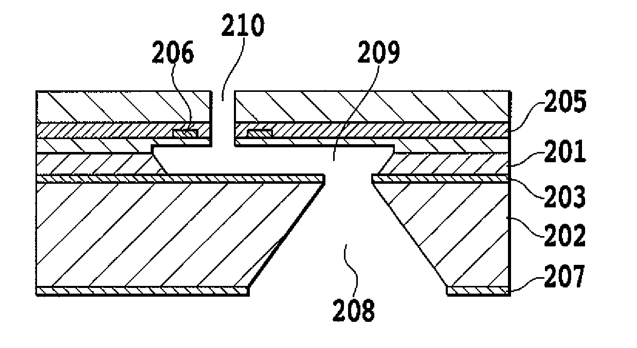
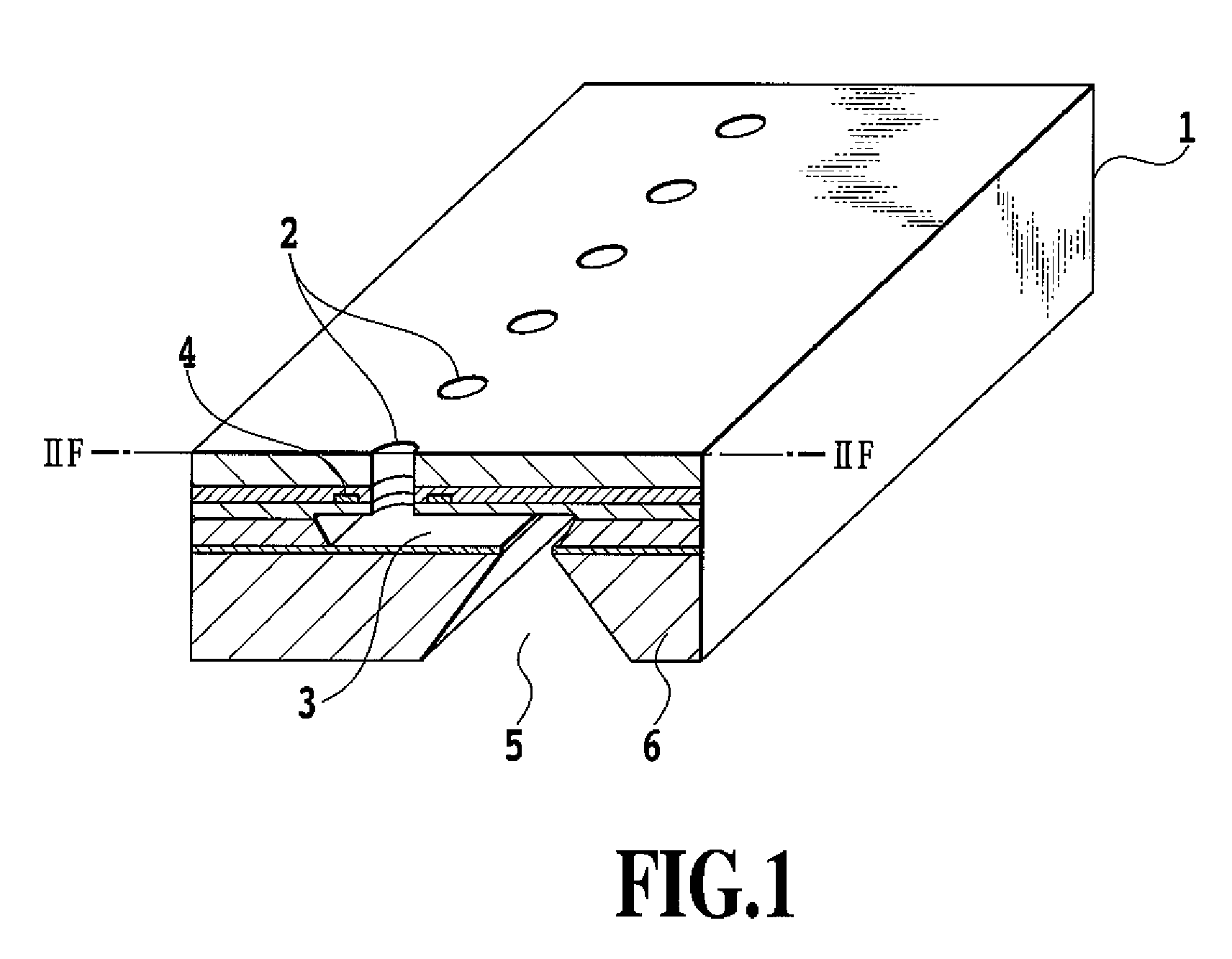
[0036]FIG. 1 is a partly exploded perspective view showing an ink jet print head in accordance with the present embodiment. An ink jet print head 1 has a plurality of ejection ports 2, a liquid channel 3, a plurality of heaters 4, and an ink supply port 5 which are all formed on a silicon substrate 6. Ink is fed from the ink supply port 5 to the liquid channel 3 and ejected from the ejection ports 2 by the thermal energy of the heaters 4 provided in the respective liquid channel 3 and serving as energy generating elements. The energy generating elements 4 are not limited to the heaters but may be piezoelectric elements or the like. In the present embodiment, each of the ejection ports 2 is provided in a corresponding area surrounded by or sandwiched between the energy generating elements 4. However, the present invention is not limited to this. Each ejection port may be located adjacent to one side of the corresponding energy generating element 4.

[0037]The ink jet print head can be ...

second embodiment

[0057]FIGS. 3A to 3F are cross section views showing a method for manufacturing an ink jet print head in accordance with a second embodiment of the present invention. The cross section is the same as FIGS. 2A to 2F. The present embodiment corresponds to an example in which two monocrystal silicon layers in an SOI substrate have different crystal directions.

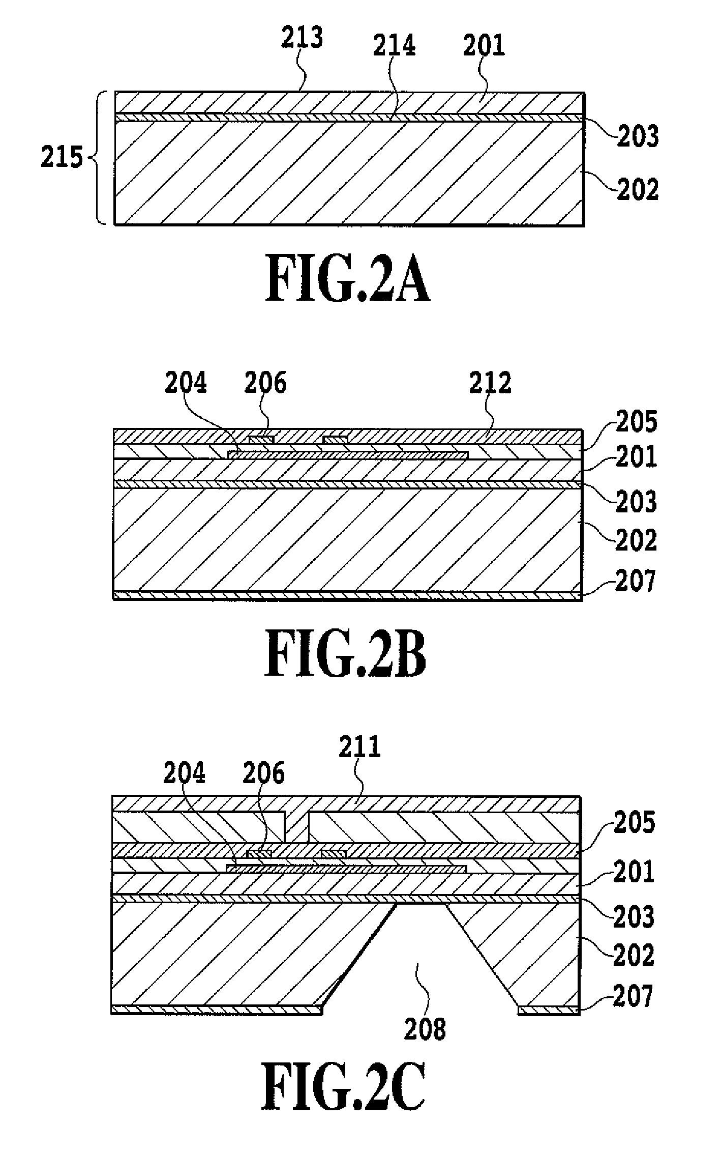
[0058]First, an SOI substrate 314 of diameter 150 mm is prepared which is manufactured by laminating a first monocrystal silicon layer, an insulating layer, and a second monocrystal silicon layer. In the present embodiment, a first monocrystal silicon layer 301 has a main surface 312 of a {100} plane and a thickness of 25 μm. An insulating layer 303 is a silicon oxide layer of thickness 0.3 μm. A second monocrystal silicon layer 302 has a main surface 313 of a {110} plane and a thickness of 600 μm.

[0059]FIG. 3A is a diagram showing an SOI substrate 314 formed of the first monocrystal silicon layer 301 made of monocrystal silicon h...

third embodiment

[0079]In the second embodiment, the first and second monocrystal silicon layers have main surface of a {100} plane and {110}, respectively. However, the present invention is not limited to this combination of monocrystal silicon layers.

[0080]In the present embodiment, the first monocrystal silicon layer has a main surface of a {110} plane, and the second monocrystal silicon layer has the main surface of a {110} plane. This allows the liquid channel to be densely arranged.

[0081]FIGS. 5A to 5F are cross section views showing a method for manufacturing an ink jet print head in accordance with a third embodiment of the present invention, and the cross section is the same as FIGS. 2A to 2F.

[0082]FIG. 5A is a diagram showing an SOI substrate of diameter 150 mm formed of a first monocrystal silicon layer 501 having a main surface 512 of a {110} plane and a thickness of 25 μm, an insulating layer 503, and a second monocrystal silicon layer 502 also having a main surface 513 of a {110} plane...


PUM

PropertyMeasurementUnit
widthaaaaaaaaaa
depthaaaaaaaaaa
thicknessaaaaaaaaaa

Abstract

The present invention provides an ink jet print head having a channel shape that meets an intended purpose, and a method for manufacturing the ink jet print head. In the method for manufacturing the ink jet print head, an SIO SOI substrate is prepared which has a first silicon layer, a second silicon layer, and an insulating layer. A sacrifice layer is formed on the first monocrystal silicon layer. An etching stop layer is formed over the sacrifice layer. An energy generating element is formed on a surface of the SOI substrate. Etching is performed on the second silicon layer and the insulating layer to form an ink supply port. The supply port is formed by etching. The first silicon layer is etched to form a liquid channel. A part of the etching stop layer is removed to form an ejection port.

Description

BACKGROUND OF THE INVENTION[0001]1. Field of the Invention[0002]The present invention relates to an ink jet print head and a method for manufacturing an ink jet print head.[0003]2. Description of the Related Art[0004]An ink jet print head used for an ink jet printing method (liquid ejection printing method) commonly comprises a plurality of fine ejection ports and a plurality of fine liquid channels formed in an orifice plate, and a plurality of liquid ejection pressure generating sections each provided in a part of the corresponding liquid channels. The ink jet print head often further comprises a supply port formed in a head substrate in communication with the liquid channels and serving as a through-hole.[0005]Such an ink jet print head has heat generating sections (heaters) in the respective channels, which are in communication with the corresponding ejection ports; each corresponding heat generating section, channel, and ejection port constitute a print element. Electric energy...

Claims


Application Information

Patent Timeline
Patent Type & Authority Patents(United States)
IPC IPC(8): B41J2/14B44C1/22
CPCB41J2/1404B41J2/1601B41J2/1628B41J2/1634B41J2/1639B41J2/1643B41J2002/1437B41J2/14137B41J2/1629B41J2/1412B41J2/14072Y10T29/49401
Inventor HAYAKAWA, KAZUHIRO
Owner CANON KK
Why Eureka
Try Eureka