Superconducting electrodynamic turbine
a superconducting, electrodynamic technology, applied in windings, magnetic holding devices, mechanical devices, etc., can solve the problems of added difficulties in deploying solar sails, difficult to deploy, etc., and achieve the effect of low cost, low cost, and simple components
- Summary
- Abstract
- Description
- Claims
- Application Information
AI Technical Summary
Benefits of technology
Problems solved by technology
Method used
Image
Examples
first embodiment
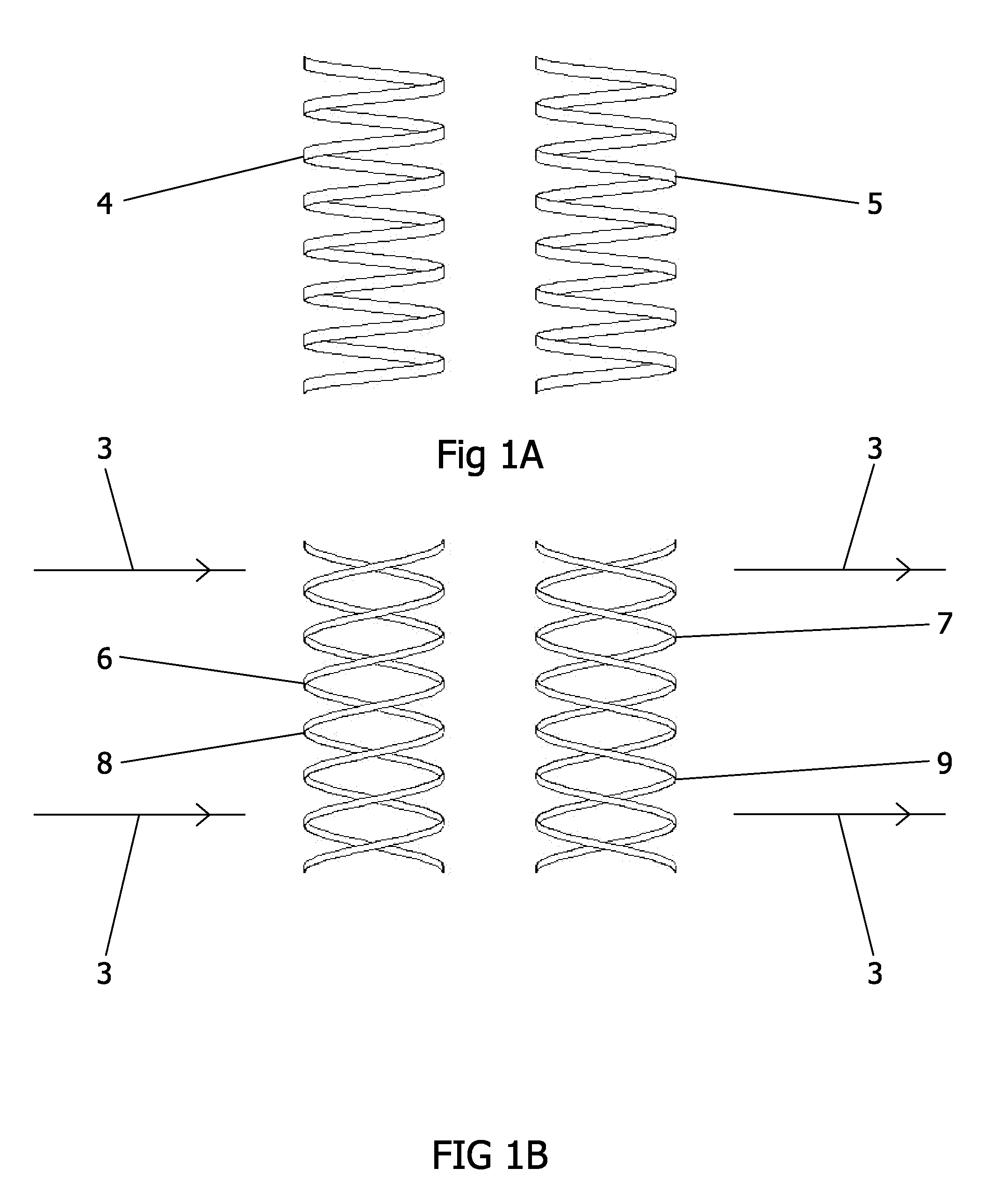
FIG. 1A—First Embodiment
[0037]FIG. 1A is a simplified illustration of the first embodiment of the SET, comprising a pivotably disposed right-handed Superconducting helix, 4 and a pivotably disposed left-handed Superconducting helix, 5. The helixes 4, 5, can consist of helically wound High Temperature Superconductor (HTS) wire, which could be American Superconductor's High Strength Plus wire, part number 5705. Other types of Superconductors, such as a plated YBCO film are also suitable as the active part of the helixes and the use of HTS wire in this embodiment is not to be construed as a limitation thereof. The HTS wire, thin film or other form of Superconductor that are the active component of the helixes has a rectangular cross-section, with the large dimension disposed parallel with the axis of the helix. The Superconducting helixes can consist of a plurality of individual discoid, wafer, or rectangular shaped sections of a Superconductor assembled into a helix shape, such that t...
second embodiment
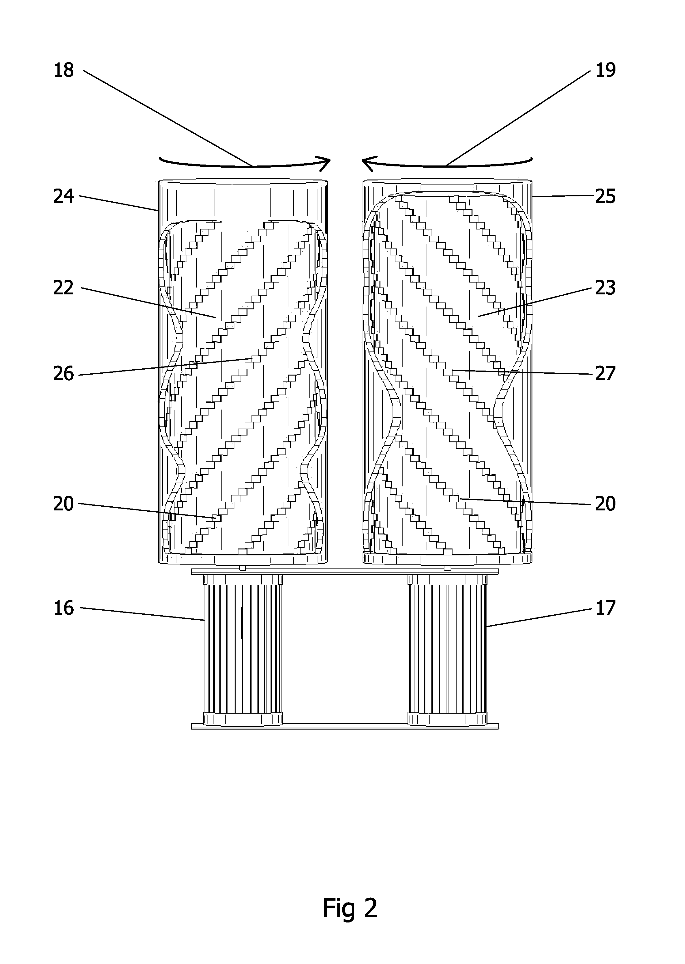
FIG. 2—Second Embodiment
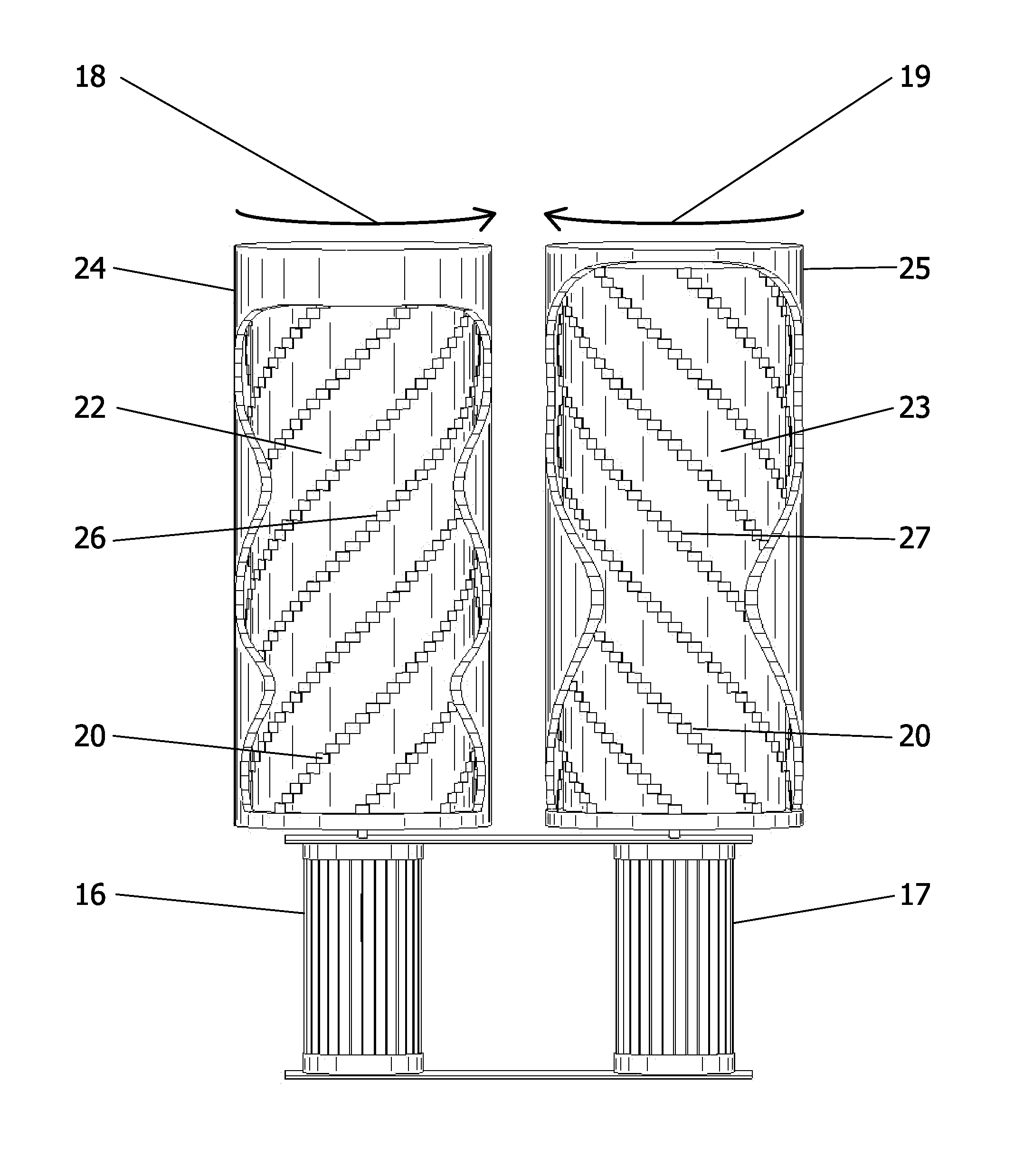
[0039]FIG. 2 illustrates two sets of helixes with opposite chirality, 26, 27 that are composed of rectangular shaped sections of a Superconductor, 20. The rectangular shaped sections can be fabricated from a high temperature Superconductor cable. The American Superconductor's High Strength Plus wire, part number 5705 that was mentioned earlier with respect to the solid helix configuration of the invention has proven to be suitable. Other types of metal clad second generation high temperature Superconductor cable may also be suitable. The rectangular shaped sections of a Superconductor are disposed tangent to and are fastened to the outer surfaces of the inner cylinders, 22, 23, that are made from fiberglass, garolite, kevlar or some other material that has sufficient strength for this application, provides the overall structural support, and provides an inner temperature insulating layer for maintaining very low temperatures inside the device.
[0040]Outer cyli...
third embodiment
FIGS. 2A AND 2B—Third Embodiment
[0043]FIG. 3A, 3B illustrate the third embodiment of the SET whereby the opposite-handed Superconducting helixes are disposed concentric. It is tubular shaped with drive pulleys at both ends. At the center axis is a shaft, 100. An inner drive pulley, 116, is located on and is free to rotate on said shaft. An outer drive pulley, 117, is supported on and is free to rotate on said inner drive pulley. An outer casing, 114, made from fiberglass, garolite, kevlar or some other material that has sufficient strength for this application, provides the overall structural support, and provides an outer temperature insulating layer for maintaining very low temperatures inside the device.
[0044]Bearing tracks 115, 118 are attached to said outer casing and provide low friction rotational support for said outer drive pulley. A tube, 112, made from fiberglass, garolite, kevlar or some other material that has sufficient strength for this application, is attached to sai...
PUM
 Abstract
Description
Claims
Application Information
 - R&D
- Intellectual Property
- Life Sciences
- Materials
- Tech Scout
- Unparalleled Data Quality
- Higher Quality Content
- 60% Fewer Hallucinations
Browse by: Latest US Patents, China's latest patents, Technical Efficacy Thesaurus, Application Domain, Technology Topic, Popular Technical Reports.
© 2025 PatSnap. All rights reserved.Legal|Privacy policy|Modern Slavery Act Transparency Statement|Sitemap|About US| Contact US: help@patsnap.com


