
Method and system for cooperative communications with minimal coordination

a cooperative communication and coordination technology, applied in pulse techniques, site diversity, coding, etc., can solve the problems of preventing reliable communication and staying at a low snr, and achieve the effects of enhancing data reliability, enhancing data reliability, and confirming the correctness of received data

Active Publication Date: 2013-11-05
TRELLIS WARE TECH
View PDF44 Cites 7 Cited by
  • Summary
  • Abstract
  • Description
  • Claims
  • Application Information

AI Technical Summary

Benefits of technology

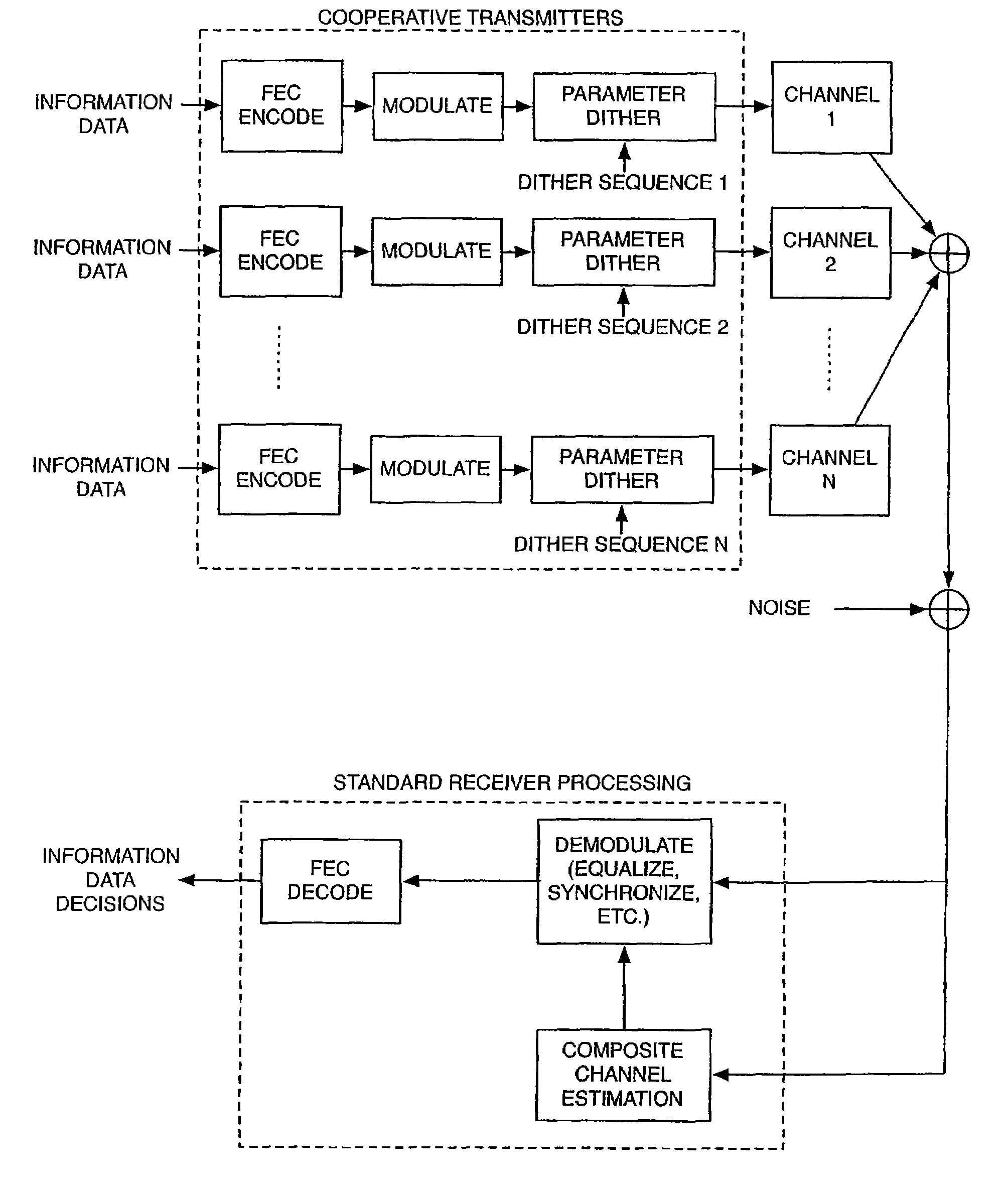
The present invention proposes a system for cooperative communication networks. The system includes a source node that sends information data to multiple transceivers. Each transceiver has a receiver to receive the data, an FEC encoder to enhance data reliability, a modulator, and a dithering mechanism. The FEC encoder rearranges the order of the encoded data to separate adjacent data for further reliability. The modulated blocks of symbols from each transceiver are dithered with a distinct pattern. The source node can apply a simple CRC code or a more complex forward error correction code, such as a Reed-Solomon block code or a convolutional code, to verify the correctness of the received data and correct errors in the channel. The FEC code is a modern code using a rate ½ F-LDPC code. The technical effects of the invention include improved data reliability and efficient error correction in cooperative communication networks.

Problems solved by technology

The primary problem with the naive uncoordinated method is that destructive interference is possible and when it occurs it is relatively stable.
That is, when a low received signal-to-noise ratio (SNR) in the composite signal is received, it will tend to stay at a low SNR prohibiting reliable communication.

Method used


Image

  • Method and system for cooperative communications with minimal coordination
  • Method and system for cooperative communications with minimal coordination
  • Method and system for cooperative communications with minimal coordination

Examples


Embodiment Construction

[0046]As a simple example of the benefits of the proposed approach, consider two cooperating transmitters, each sending a symbol sequence s[k], where k is the time index. Under a simple additive white Gaussian noise (AWGN) channel model, the composite signal model is

z[k]={A[1,k]exp(jP[1,k])+A[2,k]exp(jP[2,k])}s[k]+w[k]  (1)

where A[n,k]exp(jP[n,k]) is the complex baseband channel response from transmitter n to the receiver in amplitude-phase form (amplitude A[n,k] and phase P[n,k]), j is the square-root of −1, exp(.) is the exponential function, and w[k] is AWGN. Note that this may be expressed as

z[k]=C[k]exp(jQ[k])s[k]+w[k]  (2)

where C[k] is the composite channel amplitude and Q[k] is the composite channel phase. The instantaneous SNR of the composite signal is proportional to the square of C[k].

[0047]First consider the case of naïve uncoordinated cooperative communications. In this case, the complex channel gains are not varying with time, i.e., A[n,k]exp(jP[n,k])=A[n] exp(jP[n]). ...


PUM


Abstract

A method and system are provided in a wireless communications system comprising a plurality of nodes (users) working cooperatively. The system provides cooperative diversity by allowing nodes to actively share their antennas and other resources to obtain spatial diversity. The nodes receive the same message (information data) from a common source. Each node enhances the reliability of the message with a modern forward error correction (FEC) code, converts the FEC encoded message into an ensemble of symbols, divides the ensemble of symbols into packets, modulates, dithers and transmits the packets to a receiving node. The dithering process is performed by varying the signal amplitude, phase, frequency and / or symbol timing of the modulated packets. A unique dither pattern is assigned to each node. The receiving node captures a composite signal comprising the transmitted packets of all or most of the transmitting nodes in the cooperative communications system. Because the transmitted packets are dithered independently in phase and / or amplitude, spatial diversity is transformed into temporal diversity.

Description

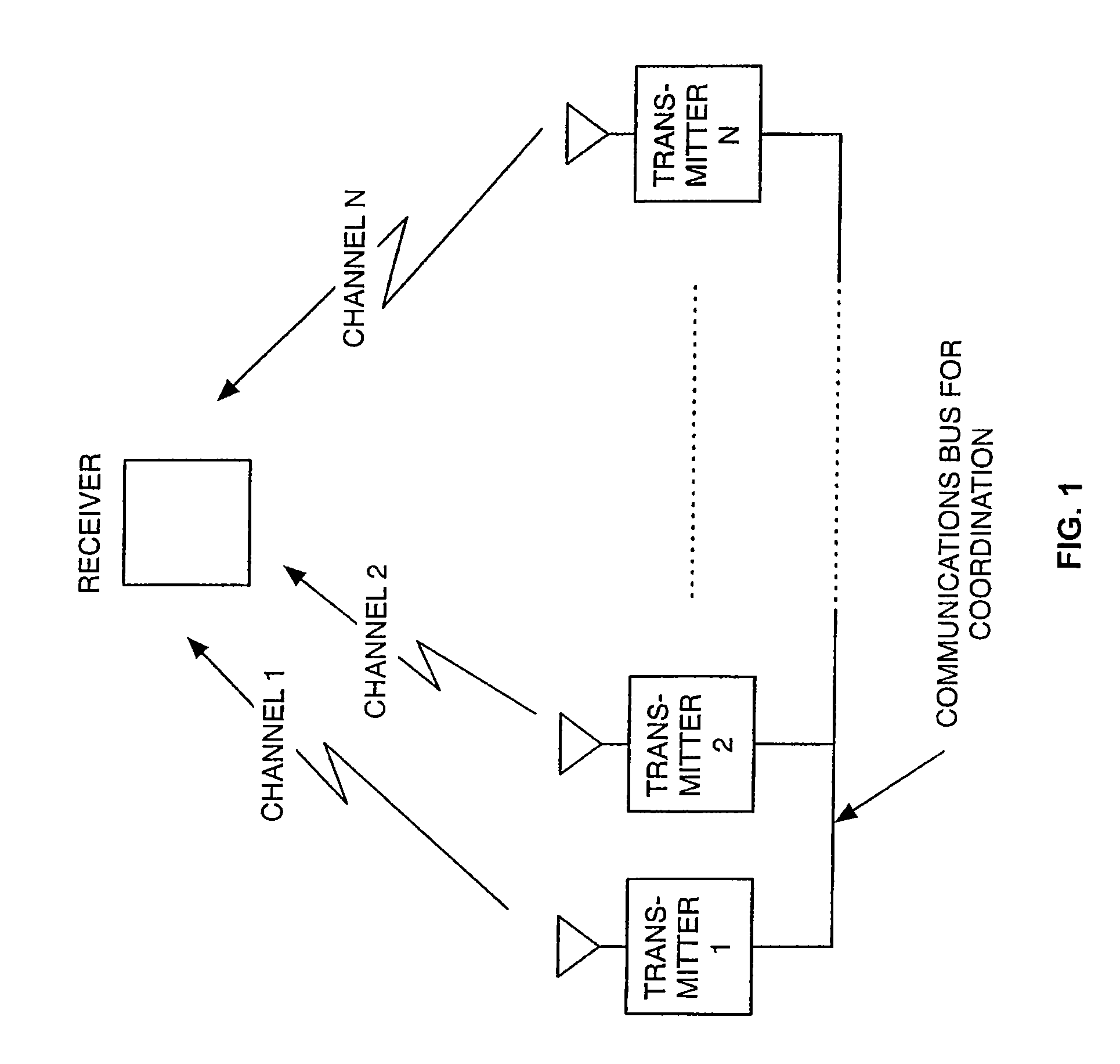
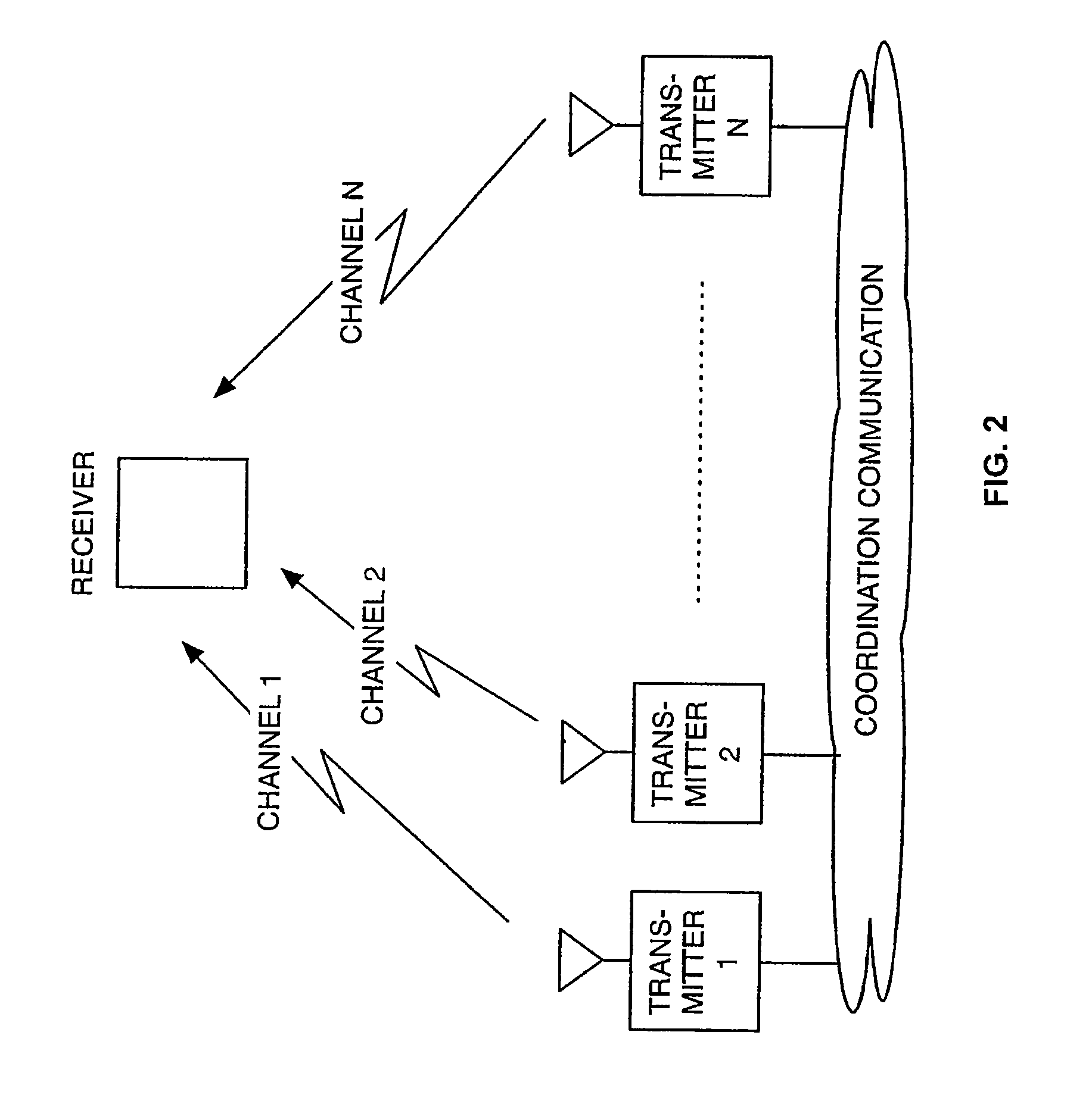
CROSS-REFERENCES TO RELATED APPLICATIONS[0001]This application is a nonprovisional application of and claiming priority to U.S. Provisional Application No. 60 / 981,452 filed Oct. 19, 2007.BACKGROUND OF THE INVENTION[0002]There is currently great interest in enabling several radio transmitters, which are not collocated, to cooperate in communicating a message to a receiver or several receivers. This concept is known as cooperative communications and it offers several advantages including increased communication range, increased robustness to channel fading and other impairments (e.g., jamming) and robustness in multi-hop routes in networks with little or no centralized control (i.e., so called ad-hoc networks).[0003]Cooperative communication is conceptually similar to transmission from multiple antennas that are collocated, or collocated antennas arrays (commonly referred to as antenna arrays). In this context the term collocated means that the transmitters, which may be complete radi...

Claims


Application Information

Patent Timeline
Patent Type & Authority Patents(United States)
IPC IPC(8): H04L27/00
CPCH04B7/026H04L1/004
Inventor CHUGG, KEITH M.JOHNSON, MARK
Owner TRELLIS WARE TECH
Learn More