Data transfer circuit and data transfer method for clock domain crossing

a data transfer circuit and clock domain technology, applied in the field of clock domain crossing circuits, can solve the problems of data not being successfully transferred from the ff operating at 200 mhz, failure to meet the requirements of 333 mhz and 200 mhz, etc., and achieves the effects of selective changes in clock combinations, fast data transfer, and fast data transfer

Inactive Publication Date: 2013-11-19
INT BUSINESS MASCH CORP
View PDF9 Cites 2 Cited by
  • Summary
  • Abstract
  • Description
  • Claims
  • Application Information

AI Technical Summary

Benefits of technology

[0012]The present invention can solve the problem of inability to correctly transfer data due to failures such as data loss in data transfer because of limited combinations of available clocks in a synchronous circuit design. Particularly, an object of the present invention is to realize a circuit and a method that enable flexible selection of a clock combination and fast data transfer between clock domains without failures such as data loss. Objects of the present invention include providing a circuit and a method for fast data transfer between clock domains that use synchronized clocks.
[0021]According to the present invention, a circuit and a method that enable flexible selection of a clock combination and fast data transfer between clock domains without failures such as data loss are realized. Particularly, a circuit and a method for fast data transfer between clock domains that use synchronized clocks are provided, and selective changes in clock combination can be addressed without modification of the circuit itself.

Problems solved by technology

However, if data passing is not sufficiently reviewed, a failure may occur in an unexpected case.
However, the technique in FIG. 1 cannot address the case of 333 MHz and 200 MHz as shown in the lower row in FIG. 4, in which the clock frequency ratio is 5:3.
However, the data is not successfully transferred from the FF operating at 200 MHz to the FF operating at 333 MHz (see clocks and data in a fourth row) with the loss of the data b and e (see data transfer indicated by dashed arrows and dashed circles).
That is, the setup time is 1 or 2 ns, resulting in severe data passing timing.
In a synchronous circuit design, combinations of available clocks are limited.
Trying to transfer data fast leads to inability to correctly transfer the data due to failures such as data loss.
The asynchronous processing such as based on double latch causes losses at the time of data passing.

Method used


Image

  • Data transfer circuit and data transfer method for clock domain crossing
  • Data transfer circuit and data transfer method for clock domain crossing
  • Data transfer circuit and data transfer method for clock domain crossing

Examples


Embodiment Construction

[0040]The best mode for implementing the present invention will be described in detail below with reference to the drawings. Embodiments below are not intended to limit the present invention set forth in claims, and not all combinations of features described in the embodiments may be essential to the solution of the present invention. The present invention can be implemented in many different aspects and should not be construed exclusively within the content of the described embodiments. Throughout the description of the embodiments, like components and elements are given like numbers.

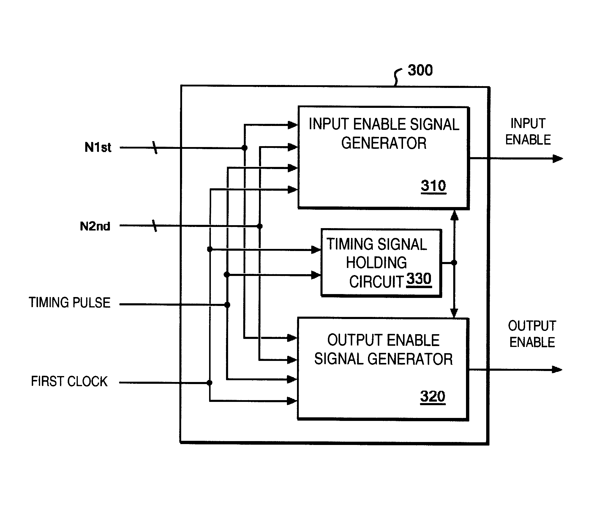
[0041]FIG. 8 shows a schematic of a data transfer circuit 100 according to an embodiment of the present invention. The data transfer circuit 100 includes a data holding circuit 200, and an enable signal generation circuit 300 connected to the data holding circuit 200. As shown in FIG. 8, the data holding circuit 200 receives an input of data from, e.g., a combinational circuit, and operates at a first ...


PUM


Abstract

A circuit that transfers data between a first clock domain using a first clock and a second clock domain using a second clock synchronized with the first clock. The circuit comprises a data holding circuit operating at the first clock, an enable signal generation circuit connected to the data holding circuit. Preferably, the data transfer circuit includes an edge signal generation circuit connected to the data holding circuit, the edge signal generation circuit generating an edge signal allowing the data holding circuit to receive and send the data when edges of the first clock and the second clock align, and applying the edge signal to the data holding circuit.

Description

CROSS REFERENCE TO RELATED APPLICATION[0001]The present application claims the benefit of priority to a Japanese Patent Application Serial Number 2010-244103 entitled “DATA TRANSFER CIRCUIT AND DATA TRANSFER METHOD FOR CLOCK DOMAIN CROSSING”, filed Oct. 29, 2010 with the Japanese Intellectual Property Office, the content of which is incorporated herein by reference in its entirety.TECHNICAL FIELD[0002]The present invention relates to data processing using clocks, and particularly to a circuit and a method for Clock Domain Crossing (hereinafter referred to as CDC), in which data is transferred across clock domains.BACKGROUND[0003]A large-scale chip such as an SoC (System on a Chip) on which various circuits coexist often uses more than one clock and therefore requires a CDC circuit design for exchanging data between different clock domains. In an asynchronous circuit design, which presupposes misalignment of clock edges, various clock combinations can be selected. However, if data pa...

Claims


Application Information

Patent Timeline
Patent Type & Authority Patents(United States)
IPC IPC(8): H03K9/00G06F3/038G06F1/04
CPCG06F1/12H03K5/00G06F13/4217
Inventor MAENO, TAKASHIMURAKAMI, MASAHIRO
Owner INT BUSINESS MASCH CORP
Why Eureka
Try Eureka