Implantable wireless accoustic stimulators with high energy conversion efficiencies

a wireless accoustic stimulator and energy conversion efficiency technology, applied in the field of receiver-stimulator, can solve the problems of high isotropy, single piezoelectric component limitation in its ability to produce high electrical output, components can be out of phase, etc., to achieve high isotropy, stimulate cardiac tissue, and efficient harvesting of acoustic power

Active Publication Date: 2013-11-19
EBR SYST
View PDF5 Cites 114 Cited by
  • Summary
  • Abstract
  • Description
  • Claims
  • Application Information

AI Technical Summary

Benefits of technology

[0012]In a first aspect, the present invention provides an implantable receiver-stimulator device which is capable of harvesting acoustic power from an acoustic field that is delivered from an acoustic source (physically separate from the receiver-stimulator device) and converting that acoustic power to electrical power to deliver electrical energy to stimulate tissue. The receiver-stimulator of the present invention is configured to be efficient, meaning it harvests all or nearly all of the acoustic power available and converts it into electrical power sufficient to stimulate cardiac tissue. In addition to efficient harvesting of acoustic power, the implantable receiver-stimulators of the present invention are also capable of functioning with a high degree of isotropy. This means that the output electrical power of the receiver-stimulator is constant or nearly constant as the receiver-stimulator's orientation is varied, relative to the propagation direction of the acoustic field transmitted by the controller-transmitter. In addition, the receiver-stimulator consists of multiple harvesting elements integrated into a mechanical structure that in aggregate provide high efficiency and a high degree of isotropy.

Problems solved by technology

However, this comes at the expense of isotropy.
Therefore, a receiver-stimulator consisting of a single piezoelectric component is limited in its ability to produce high electrical output and exhibit high isotropy.
The piezoelectric components produce AC electrical power which is not optimized for tissue stimulation.
Furthermore, the AC electrical power produced by separate piezoelectric components can be out of phase, making it difficult to combine these outputs directly without loss of power Rectifying these outputs prior to combining them reduces this power loss.

Method used


Image

  • Implantable wireless accoustic stimulators with high energy conversion efficiencies
  • Implantable wireless accoustic stimulators with high energy conversion efficiencies
  • Implantable wireless accoustic stimulators with high energy conversion efficiencies

Examples


Embodiment Construction

[0036]In the following description, for purposes of explanation, numerous specific details are set forth in order to provide a thorough understanding of the invention. It will be apparent, however, to one skilled in the art that the invention can be practiced without these specific details.

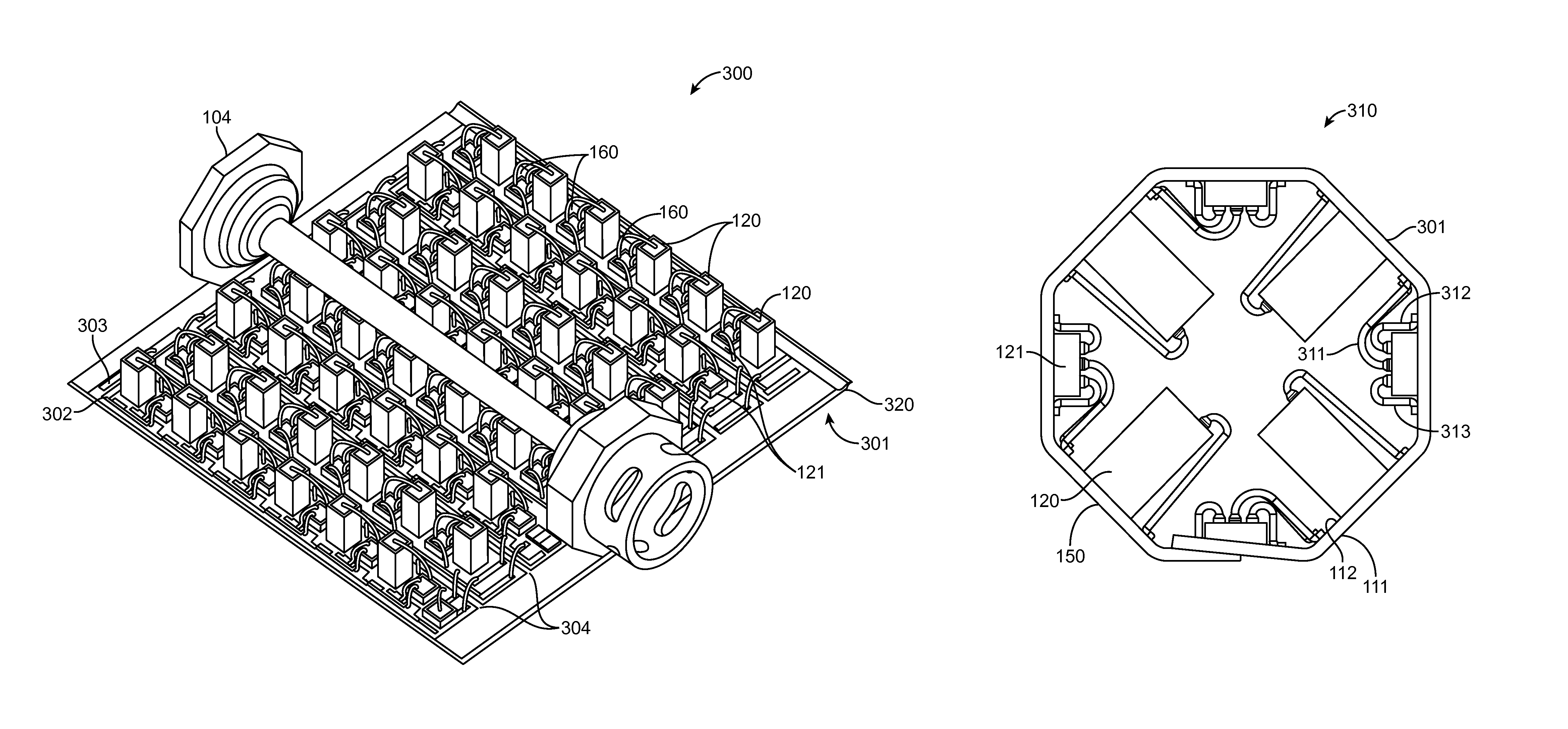
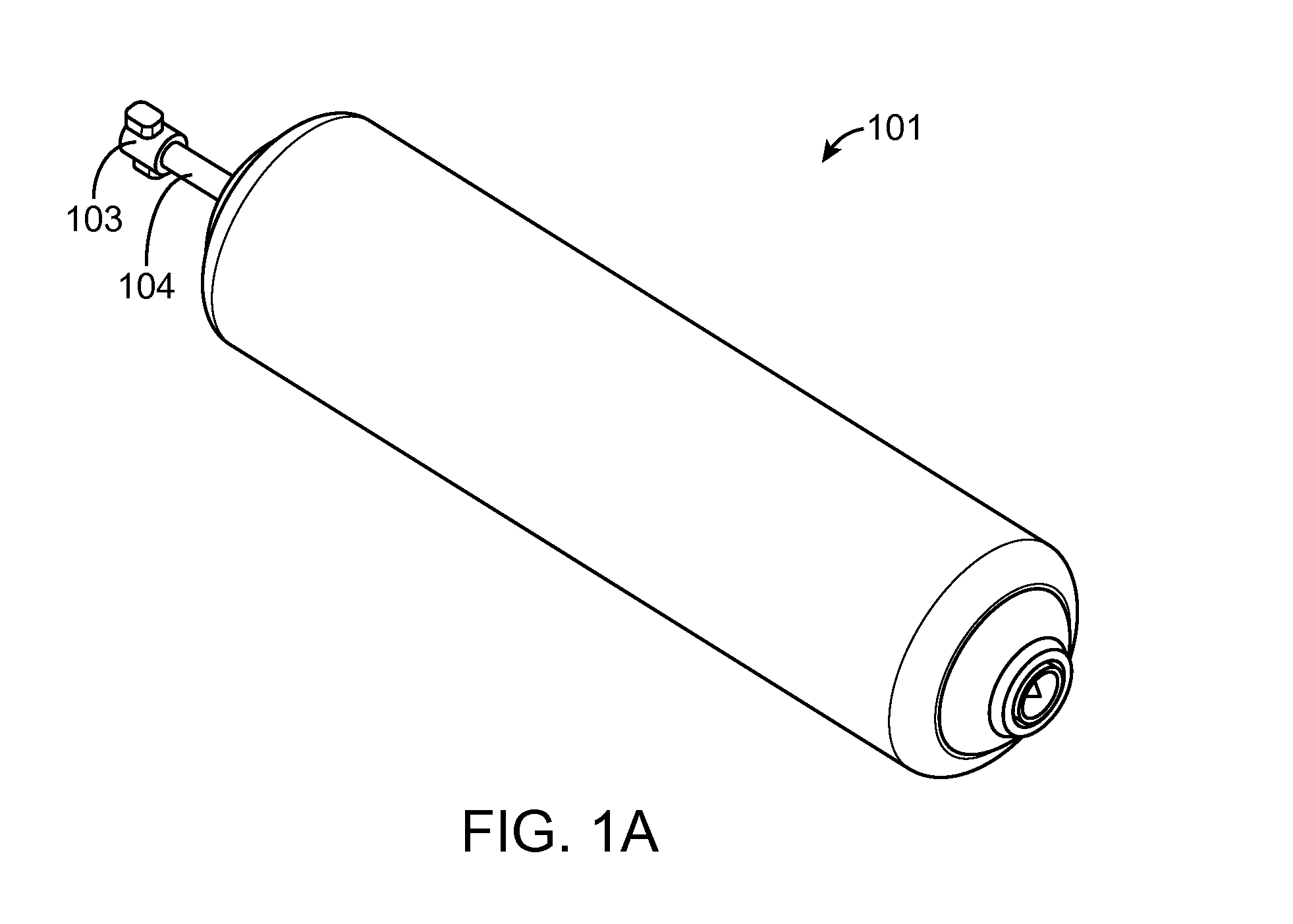
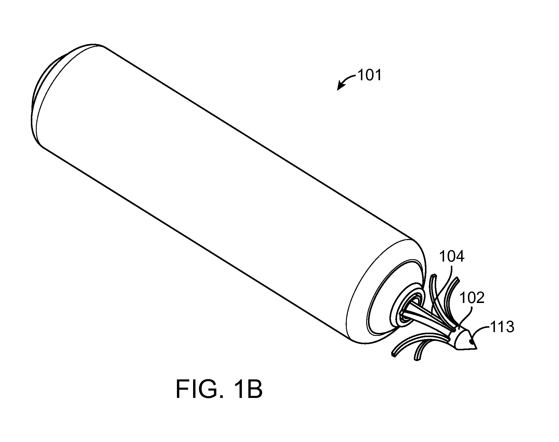
[0037]In a first aspect, the present invention provides an implantable receiver-stimulator (hereinafter also abbreviated as “R-S” and also referred to as “stimulator”) device which is capable of wirelessly harvesting acoustic power from an acoustic field delivered from an acoustic source physically separate from the R-S, and converting that acoustic power to electrical power, rectifying the electrical power, and delivering an electrical output between two stimulation electrodes.

[0038]FIGS. 1A-1D are diagrams illustrating an implantable receiver-stimulator 101, constructed in accordance with the principles of the present embodiments. FIGS. 1C and 1D are cross-sectional views of the R-S 101 device a...


PUM

PropertyMeasurementUnit
voltagesaaaaaaaaaa
lengthaaaaaaaaaa
lengthaaaaaaaaaa

Abstract

Receiver-stimulator with folded or rolled up assembly of piezoelectric components, causing the receiver-stimulator to operate with a high degree of isotropy are disclosed. The receiver-stimulator comprises piezoelectric components, rectifier circuitry, and at least two stimulation electrodes. Isotropy allows the receiver-stimulator to be implanted with less concern regarding the orientation relative the transmitted acoustic field from an acoustic energy source.

Description

CROSS-REFERENCE TO RELATED APPLICATION[0001]This application is a continuation-in-part of U.S. patent application Ser. No. 12 / 721,483, filed Mar. 10, 2010, which is a continuation-in-part of International (PCT) Patent Application No. PCT / US2009 / 038258, filed Mar. 25, 2009, which claimed the benefit of U.S. Provisional Patent Application No. 61 / 039,340, filed on Mar. 25, 2008, the disclosures of which are incorporated herein by reference.BACKGROUND OF THE INVENTION[0002]1. Field of Invention[0003]The present invention relates to a wireless acoustic stimulation system for stimulating biological tissue and, in particular, for a receiver-stimulator that converts an acoustic field into electrical power at high energy conversion efficiency to deliver stimulation energy to tissue. The receiver-stimulator has highly isotropic performance based on the mechanical and, electrical arrangement of multiple acoustic power harvesting elements in the receiver-stimulator unit.[0004]2. Description of ...

Claims


Application Information

Patent Timeline
Patent Type & Authority Patents(United States)
IPC IPC(8): A61N1/375
CPCA61N1/3787H01L41/113H02N2/181H02N2/186H02N2/188A61N1/02H01L41/25A61N1/3756A61N1/362A61N1/37205A61B2560/0214Y10T29/42A61N1/3758H10N30/30H10N30/03A61N1/05
Inventor MOORE, DAVID F.MOHR, PAULWILLIS, N. PARKERBRISKEN, AXEL F.
Owner EBR SYST
Why Eureka
Try Eureka