Deterioration diagnostic device for an exhaust gas purifier

a technology of exhaust gas purifier and diagnostic device, which is applied in the direction of electrical control, process and machine control, instruments, etc., can solve the problems of poor accuracy of techniques, deterioration of catalysts, and poor influence on the environment, so as to improve detection accuracy, easy to generate, and easy to detect

Active Publication Date: 2013-11-26
HONDA MOTOR CO LTD
View PDF17 Cites 6 Cited by
  • Summary
  • Abstract
  • Description
  • Claims
  • Application Information

AI Technical Summary

Benefits of technology

[0009]According to the present invention, there is provided a deterioration diagnostic device for diagnosing a degradation condition of an exhaust gas purifier disposed in an exhaust passage in an internal-combustion engine based on output of an exhaust gas sensor that is disposed downstream of the exhaust gas purifier. The device includes detecting-signal generating means for generating a detecting-signal having particular frequency components and multiplying the generated detecting-signal to a basic fuel injection amount so as to calculate a fuel injection amount and exhaust gas purifier evaluating means for extracting a frequency response corresponding to the detecting-signal from an output of the exhaust gas sensor of the engine, the output being in response to the calculated fuel injection amount, so as to determine a condition of the exhaust gas purifier based on the extracted frequency response. According to this invention, a proportion of the detecting-frequency components contained in the exhaust gas can be kept at a high level because the fuel amount multiplied by the detecting-signal having a specific frequency is supplied. Besides, in such situation, the condition of the exhaust gas purifier can be diagnosed based on the frequency response in the frequency of the output of the exhaust gas sensor, so that a proportion of noise elements contained in the exhaust gas can be easily decreased and precision for determining the deterioration of the exhaust gas purifier can be improved.
[0010]According to one aspect of the invention, the detecting-signal to be multiplied to the basic fuel injection amount is a signal obtained by adding a single trigonometric function wave or a composite wave formed by two or more trigonometric function waves to a predetermined offset value. According to this aspect of the invention, the response of the specific frequency can be used for evaluating the purifier by using the signal that can be easily generated to have the sufficient proportion of the frequency components for the detection while maintaining the magnitude of the detecting-frequency components in the exhaust gas, so that the detection precision for the deterioration of the exhaust gas purifier can be further improved. Besides, the composite wave formed by two or more trigonometric function waves each having different frequency is given in such operating range where detection is especially difficult, so that the response of two or more frequencies can be used to determine the condition of the exhaust gas purifier. The detection precision of the deterioration failure of the exhaust gas purifier can be further improved because the trigonometric function waves are composed to form a desired specific waveform that allows easy determination of the condition of the exhaust gas purifier and such composed trigonometric function wave is reflected in the fuel injection amount.
[0011]According to another aspect of the invention, the exhaust gas purifier evaluating means determinates the condition of the exhaust gas purifier when a predetermined time elapses since the fuel injection amount has been supplied to the engine. According to this aspect of the invention, the determination of the exhaust gas purifier condition can be performed stably by avoiding such unstable state of the exhaust gas air-fuel ratio that may appear at the time immediately after the detecting-signal has been reflected on the fuel. Accordingly, the detection precision for the deterioration of the exhaust gas purifier can be further improved.

Problems solved by technology

However, as the usage time of the catalyst passes on, an effective surface area of the catalyst gradually decreases, resulting in deterioration of the catalyst.
When the deterioration increases, purification of the pollutants does not work properly and a proportion of the pollutants in the exhaust gas emitted to the atmosphere increases, which may exert a bad influence upon the environment.
However, this technique has a problem of poor accuracy because it determines the catalyst capability based on only the positive value signal of the remaining signal.

Method used


Image

  • Deterioration diagnostic device for an exhaust gas purifier
  • Deterioration diagnostic device for an exhaust gas purifier
  • Deterioration diagnostic device for an exhaust gas purifier

Examples


Embodiment Construction

1. Description of Functional Blocks

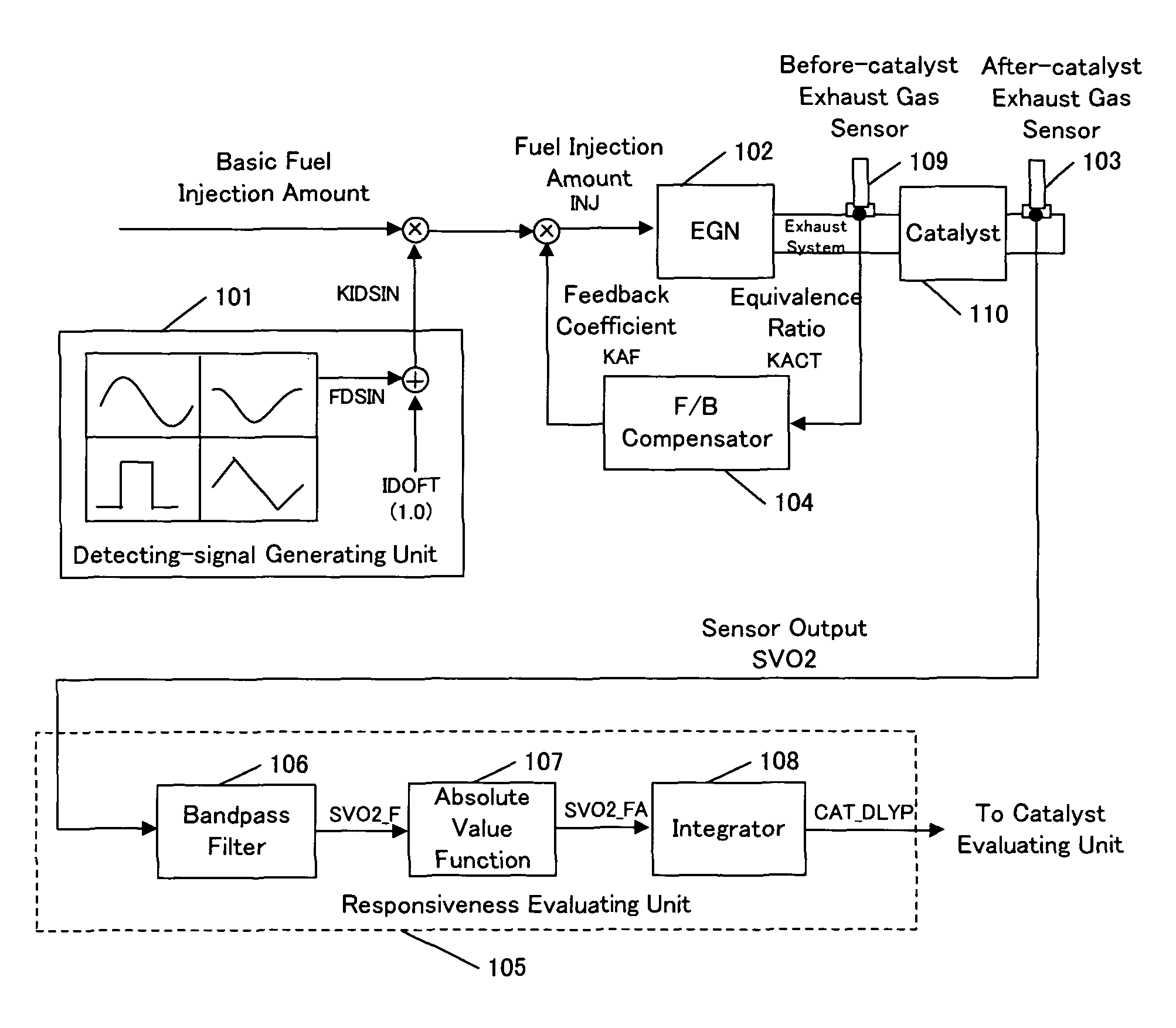
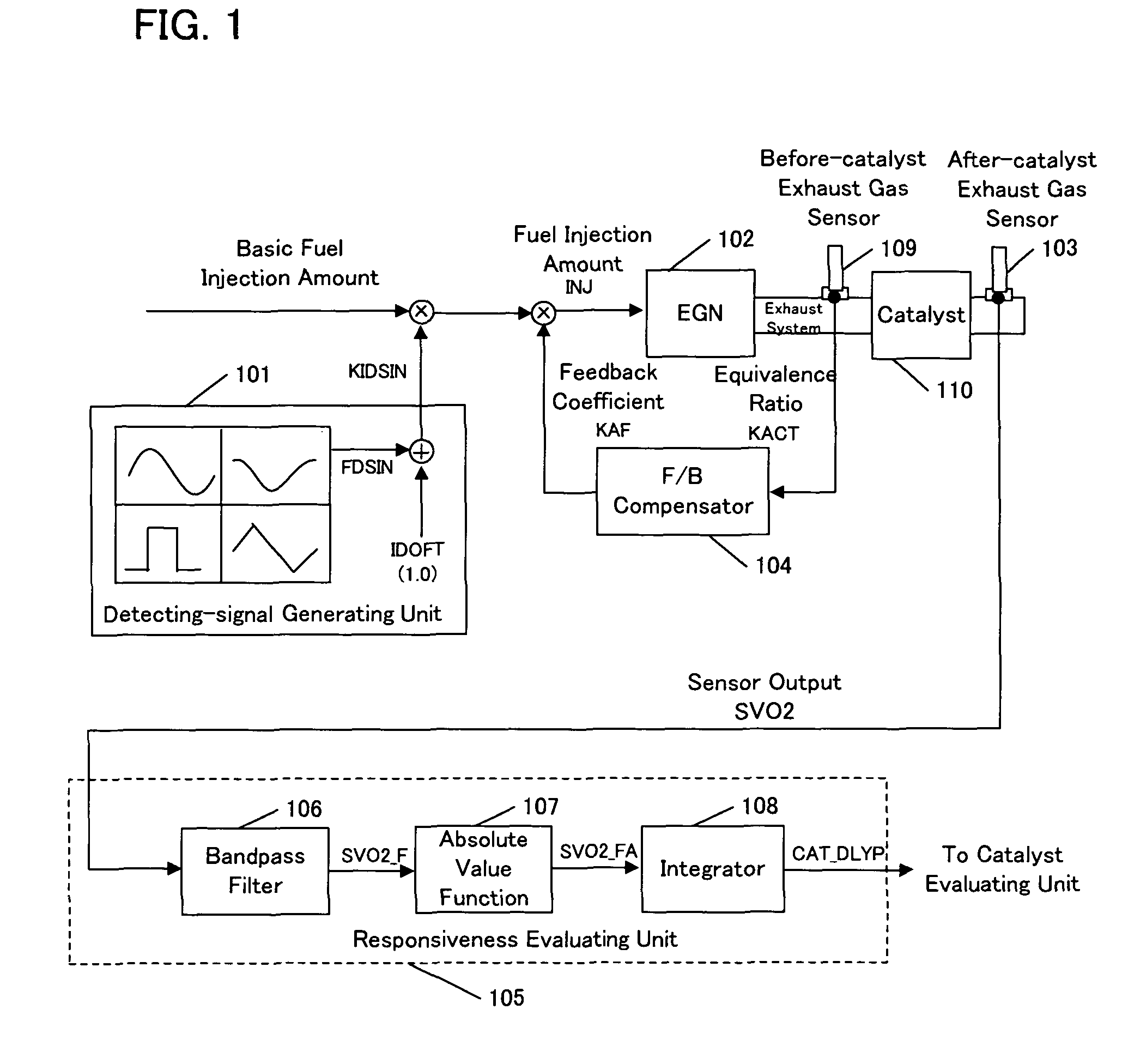
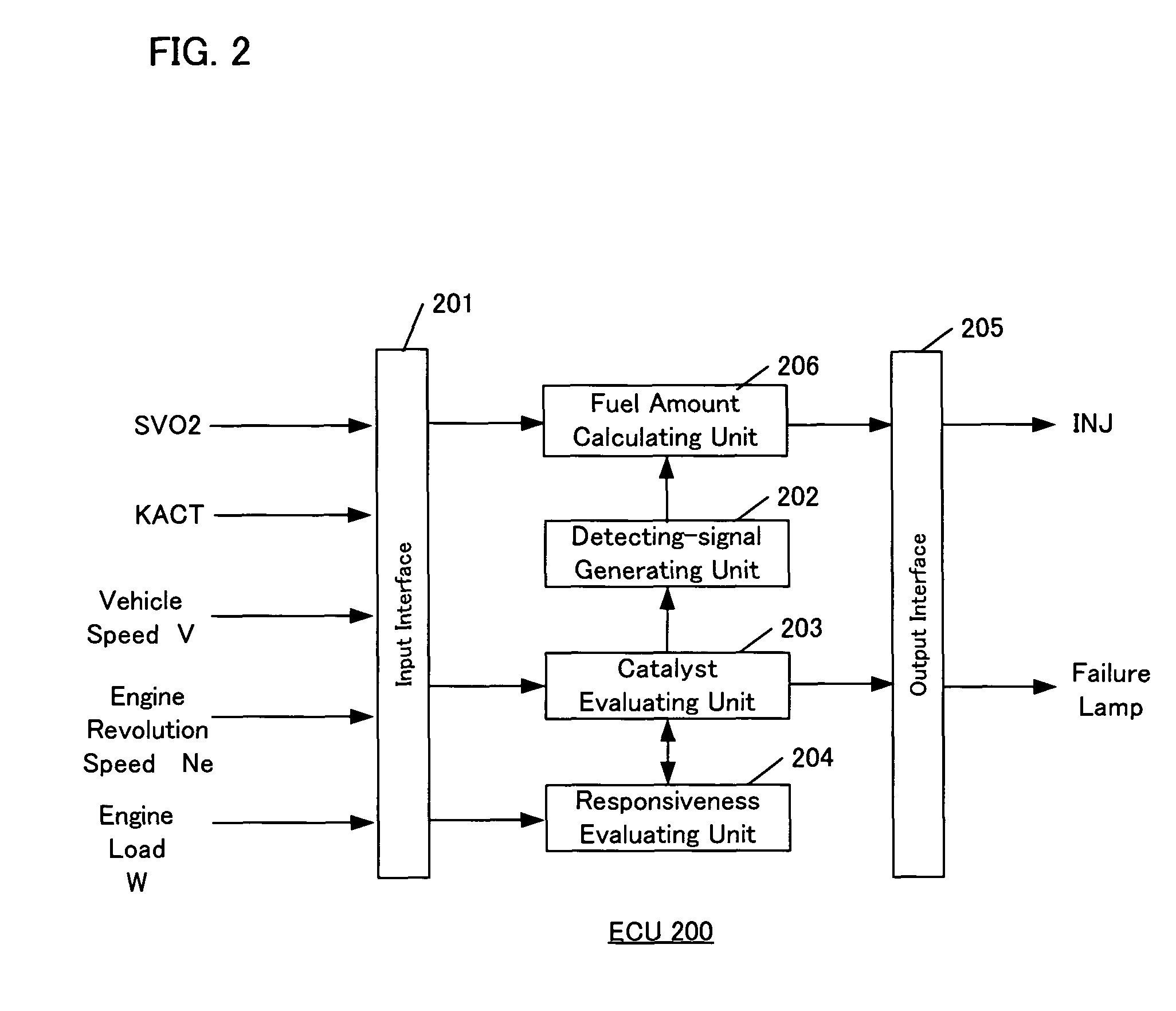
[0025]Each functional block will be described with reference to FIG. 1 and FIG. 2. FIG. 1 is a schematic diagram of an overall structure for describing a concept of the present invention.

[0026]A detecting-signal generating unit 101 has a function of generating a predetermined detecting-signal KIDSIN in which a trigonometric function wave FDSIN or the like is superimposed on an offset value IDOFT. A responsiveness evaluating unit 105 has a function of performing a bandpass filtering upon an output from an after-catalyst exhaust gas sensor 103, then converting the filtered value to an absolute value, further integrating the converted values over a predetermined time period and finally transmitting the integral value to a catalyst evaluating unit. The output of the after-catalyst exhaust gas sensor 103 may be, for example, an equivalence ratio KACT which is a linear AF (LAF) sensor output, a voltage SVO2 of an oxygen sensor output, an output of a hydr...


PUM


Abstract

The invention provides a deterioration diagnostic device for diagnosing a degradation condition of an exhaust gas purifier disposed in an exhaust passage in an engine based on a sensor value of an exhaust gas sensor that is disposed downstream of the purifier. The device includes detecting-signal generating unit for generating a detecting-signal having particular frequency components and multiplying the generated signal to a basic fuel injection amount so as to calculate a fuel injection amount and exhaust gas purifier evaluating for extracting a frequency response corresponding to the detecting-signal from an output of the exhaust gas sensor of the engine, the output being in response to the calculated fuel injection amount, so as to determine a condition of the purifier based on the extracted frequency response.

Description

BACKGROUND OF THE INVENTION[0001]The present invention relates to a device for determining a deterioration condition of an exhaust gas purifier disposed in an exhaust passage in an internal-combustion engine (hereinafter referred to as an “engine”).[0002]An exhaust gas purifier (catalyst) is disposed in an exhaust passage of an engine of a vehicle in order to purify exhaust gas from the engine. The catalyst purifies the exhaust gas by oxidizing or reducing hydrocarbon HC, nitrogen oxide NOx and carbon monoxide CO which are three major pollutants discharged from the engine.[0003]However, as the usage time of the catalyst passes on, an effective surface area of the catalyst gradually decreases, resulting in deterioration of the catalyst. When the deterioration increases, purification of the pollutants does not work properly and a proportion of the pollutants in the exhaust gas emitted to the atmosphere increases, which may exert a bad influence upon the environment.[0004]Therefore, it...

Claims


Application Information

Patent Timeline
Patent Type & Authority Patents(United States)
IPC IPC(8): F01N3/00F01N3/20F01N11/00F02D45/00F02D41/02F02D41/14
CPCF01N11/007F02D41/1454F02D41/0235F02D41/1456Y02T10/47Y02T10/40
Inventor MAKI, HIDETAKA
Owner HONDA MOTOR CO LTD
Why Eureka
Try Eureka