Projection display device with a cooling air fan

a technology of projection display and cooling air fan, which is applied in the direction of projectors, optics, instruments, etc., can solve the problems of whitening, shortened life, and a rupture, and achieve the effect of cooling the top of the light source lamp efficiently, excellent effect of preventing whitening, and shortened li

Active Publication Date: 2013-12-03
PANASONIC CORP
View PDF9 Cites 2 Cited by
  • Summary
  • Abstract
  • Description
  • Claims
  • Application Information

AI Technical Summary

Benefits of technology

[0021]The present invention is intended to solve the above problems, and it is an object of the present invention to provide a projection display device with a simple configuration that allows the top of a light source lamp to be cooled efficiently regardless of installation posture, prevents the bottom of the light source lamp from being overcooled, and allows both lateral sides of the light source lamp to be cooled at an optimum temperature.
[0024]With this configuration, due to the simple configuration of the air duct having the control valve that is rotated around a supporting axis by the action of gravity depending on a posture of the light source cooling unit, thereby controlling a cooling wind direction, it is possible to cool the top of the light source lamp efficiently, and prevent the bottom of the light source lamp from being overcooled regardless of the installation posture of the projection display device. Further, it is possible to cool both lateral sides of the light source lamp at an optimum temperature, and therefore, it is possible to achieve an excellent effect of preventing whitening, a shortened life, and a rupture as well as blacking and lower brightness of the light source.
[0025]Further, since only one fan is required to provide cooling regardless of installation posture, it is possible to reduce the size and cost of the projection display device, and further to reduce noise due to efficient cooling.

Problems solved by technology

When the light source lamp has an excessively high temperature, problems such as whitening, a shortened life, and a rupture occur.
To the contrary, when the light source lamp has an excessively low temperature, problems such as blacking and lower brightness of the light source occur.
For this reason, even with the configuration for cooling the top of the light source lamp efficiently, the projection display device is caused to cool predominantly at the bottom of the light source lamp depending on its installation posture, i.e., if the projection display device is turned upside down, resulting in an excessively low temperature at the bottom of the light source lamp.
Similarly, when the projection display device is used in a posture for projecting an image in a vertically upward direction, a posture for projecting an image in a vertically downward direction, or a posture therebetween, portions other than the top of the light source lamp are overcooled, which causes blacking and lower brightness of the light source.
As a result, the above-described phenomena are worsened.
However, it is necessary to form the air duct for cooling a light source at both the top and bottom of the concave mirror, which makes the device larger.
However, when the projection display device is directed vertically upward or vertically downward to project an image, it is impossible to cool the top of the light source lamp.
Additionally, in a certain installation posture, the light source lamp is cooled excessively at its bottom.

Method used


Image

  • Projection display device with a cooling air fan
  • Projection display device with a cooling air fan
  • Projection display device with a cooling air fan

Examples


embodiment 1

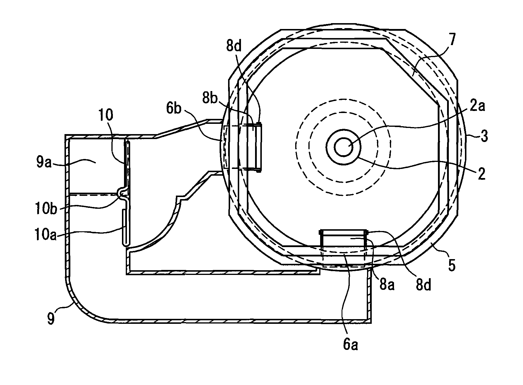
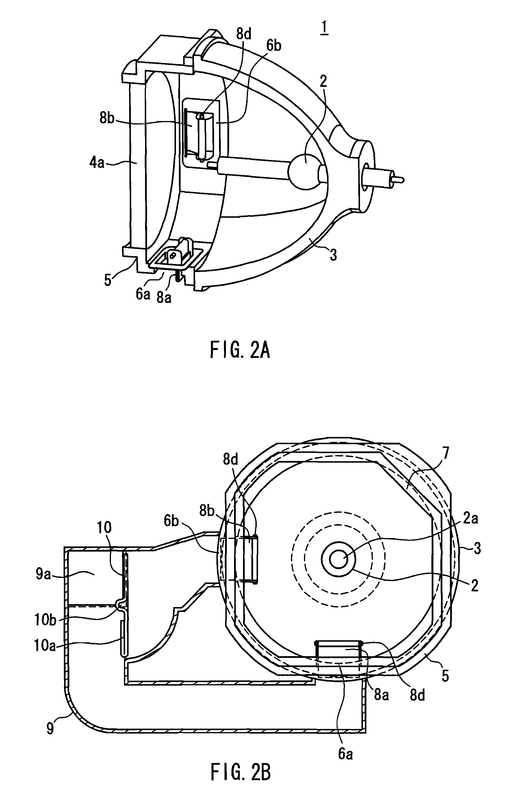
[0094]FIGS. 2A to 2C show a schematic configuration of a light source unit included in a projection display device according to Embodiment 1 of the present invention. Specifically, FIG. 2A is a cross-sectional perspective view, FIG. 2B is a front view showing a cross-section of an air duct provided at the light source unit, and FIG. 2C is a view for explaining an operation of an air control baffle. FIGS. 3A-3C to 6A-6C show relationships between an installation posture of the projection display device and a flow of cooling air. Specifically, FIGS. 3A to 6A are side views showing installation postures of the projection display device, FIGS. 3B to 6B are front views showing in partially cross-section the opening / dosing of a valve in the respective installation postures, and FIGS. 3C to 6C are side cross-sectional views showing flows of cooling air in a lamp in the respective installation postures.

[0095]A light source unit 1 includes a light source lamp 2, a substantially cylindrical c...

embodiment 2

[0117]FIG. 7 is a view showing a configuration of a rotary valve portion included in a projection display device according to Embodiment 2 of the present invention. A configuration and an operation for cooling a light source lamp are the same as those in Embodiment 1, and thus descriptions thereof will not be repeated.

[0118]In the figure, a branch switching valve 13 provided in an air duct 12 includes an axis 13a vertical to the air duct 12 and the direction of gravity, a wall plate 13b functioning to switch a flow rate, and a barycenter 13c located at a position away from the axis 13a, and is rotated around the axis 13a under its own weight.

[0119]With this configuration, the problem involved in Embodiment 1 can be solved. That is, in Embodiment 1, since the air blowing ports 6a and 6b are provided at different distances from the entrance 9a of the air duct 9, the fan has a different air flow resistance, resulting in a different cooling capability. On the other hand, the branch swit...

embodiment 3

[0122]FIGS. 8A to 8D are views showing installation postures of a projection display device and configurations of a rotary valve portion included therein according to Embodiment 3 of the present invention. FIGS. 8A and 8B correspond to each other, and FIGS. 8C and 8D correspond to each other. A configuration and an operation for cooling a light source lamp are the same as those in Embodiment 1, and thus descriptions thereof will not be repeated.

[0123]In the figures, two branch switching valves 15 and 16 respectively having axes 15a and 16a vertical to an air duct 14 and the direction of gravity are provided in the air duct 14. The valves have weight portions 15b and 16b, respectively.

[0124]When the projection display device 11 is installed in a posture rendering the position of the projection lens 11a as shown in FIG. 8A, the branch switching valves 15 and 16 respectively are rotated around the axes 15a and 16a so that the weight portions 15b and 16b are oriented downward as shown i...


PUM


Abstract

A projection display device that includes: a light source unit 1 that includes a discharge lamp 2 as a light source; an image formation unit; a projection optical system; and a light source cooling unit that cools the light source unit. The light source unit is disposed so that a lamp axis that connects two discharge electrodes of the discharge lamp is orthogonal to a projecting direction of the projection optical system, and the light source unit includes: a concave mirror 3; and a transparent part 4 that covers an opening of the concave mirror. The light source cooling unit includes: a blowing fan that supplies cooling air; a plurality of air blowing ports 6a and 6b disposed at the concave mirror or a connecting part that connects the concave mirror and the transparent part; an air duct 9 that connects the air blowing ports and the blowing fan; a branch switching valve 10a that is disposed in the air duct and switches between a plurality of branch flow paths so as to allow the cooling air to flow therethrough; and a control valve that is provided for each of the air blowing ports and rotated around a supporting axis by the action of gravity depending on a posture of the light source cooling unit, thereby controlling a wind direction so that the cooling air is blown from above the discharge lamp. The top of the light source lamp is cooled effectively regardless of the installation posture of the projection display device.

Description

BACKGROUND OF THE INVENTION[0001]1. Field of the Invention[0002]The present invention relates to a projection display device such as a projector that includes a cooling device for cooling an illuminant of a light source. More specifically, the present invention relates to a projection display device that always is capable of cooling a high-temperature portion of a light source lamp even in various installation postures.[0003]2. Description of Related Art[0004]Conventionally, a projection display device such as a projector includes a light source lamp that emits light for projecting and displaying an image displayed on a display device such as a liquid crystal panel. This light source lamp is filled with mercury, an inert gas, a metal halide, and the like.[0005]In this projection display device, when a predetermined voltage is applied to electrodes of the light source lamp, a discharge arc occurs, and the gas filled in the light source lamp starts to be convected.[0006]The discharge ...

Claims


Application Information

Patent Timeline
Patent Type & Authority Patents(United States)
IPC IPC(8): G03B21/18
CPCG03B21/16
Inventor NAMBA, SHUYAMAGISHI, SHIGEKAZUFUSHIMI, YOSHIMASAYAMASHITA, NAOKO
Owner PANASONIC CORP
Why Eureka
Try Eureka