Laser-marking film

a laser marking and film technology, applied in secondary cell servicing/maintenance, instruments, thermography, etc., can solve the problems of insufficient heat generation, difficult to form a layer for laser marking that exhibits homogeneous laser absorption, and difficult to form a layer for laser marking, so as to improve the vividness of laser markings and reduce the cost. , the effect of more vivid laser markings

Active Publication Date: 2013-12-03
TOYO SEIKAN KAISHA LTD
View PDF12 Cites 6 Cited by
  • Summary
  • Abstract
  • Description
  • Claims
  • Application Information

AI Technical Summary

Benefits of technology

[0022]If the laser-marking film of the invention is irradiated with a laser beam for laser marking, the portion irradiated with the laser beam in the ink layer formed in the film generates heat, and the resin component of the irradiated portion is carbonized and is discolored into black forming a vivid marking in the ink layer.
[0023]Further, the laser-marking film of the present invention is very inexpensive as compared to those having an ink layer formed by using, for example, a pearl pigment and, therefore, makes it possible to greatly decrease the cost.
[0024]Further, the packing materials (e.g., pouch, etc.) for containing a variety of kinds of contents must display correct information of the contents. The laser-marking film of the present invention is capable of vividly forming bar codes and character images for displaying a variety kinds of information by the irradiation with a laser beam, and is very useful for the packing materials.
[0025]In the present invention, the reddish brown iron oxide is an iron oxide pigment which chiefly comprises a —Fe2O3 and of which the color is adjusted to be reddish brown by adjusting the particle diameter thereof. Its average color tone assumes an L*-value of 40, an a*-value of 25 and a b*-value of 17 (average values with n=3) in the L*a*b* color system. The above values are measured in compliance with the method specified under the JIS Z 8722 and, in the present invention, are measured by using a measuring instrument that complies with the above JIS, i.e., by using a spectroscopic color-difference meter SE2000 manufactured by Nippon Denshoku Industries Co, Ltd.
[0026]So far, it has been proposed to use the reddish brown iron oxide (red iron oxide) and the yellow iron oxide as a laser beam-absorbing agent, and it has been urged to further improve the vividness of the laser markings that are formed by irradiating the ink layer in which the above pigments are dispersed with a YAG laser beam of a wavelength of 1064 nm. By using the ink layer formed by using an ink blended with the iron oxide and, specifically, with the reddish brown iron oxide in accordance with the present invention, on the other hand, it was made possible to form more vivid laser markings by the irradiation with the same laser beam as demonstrated in the Experimental Examples appearing layer.
[0027]It is, further, important that the laser-marking film of the present invention is provided with a white underlying layer between the ink layer in which the above iron oxide is dispersed in a resin binder and the base film. Provision of the underlying layer makes it possible to form a very vivid laser marking. That is, when the ink layer is irradiated with the laser beam, the beam reflected by the white underlying layer enters into the ink layer whereby the laser beam is sufficiently absorbed by the iron oxide. As a result, heat is generated in large amounts to form very vivid laser markings. If the ink layer in which the iron oxide is dispersed is formed directly on the base film without forming the above white underlying layer, the formed laser marking has poor vividness.

Problems solved by technology

If it is attempted to form a layer for printing laser markings by using, for example, a gravure ink in which an organic pigment or dye is dispersed, the heat is not sufficiently generated despite the layer is irradiated with a laser beam because of a low laser beam absorption and, therefore, images for representing the data are not vividly formed.
However, the inks dedicated to the laser marking in which the above pearl pigment is dispersed, have a problem that it is difficult to form a layer for laser marking that exhibits homogeneous laser absorption.
That is, the pearl pigment exhibits high laser beam absorbability but disperses poorly.
Therefore, if the layer for laser marking is formed by using the ink in which the pearl pigment is dispersed, the layer assumes irregular thickness and the pearl pigment disperses unhomogeneously causing variation in the laser-absorbing property.
If compared with the pearl pigment, however, the metal oxides shown by the above patent documents little absorb the laser beam (usually long wavelengths) for forming laser markings.
Therefore, the inks in which the metal oxides are dispersed are not still capable of forming vivid images upon the irradiation with the laser beam.

Method used


Image

  • Laser-marking film
  • Laser-marking film

Examples


experimental examples

[0063]The present invention is described by the following experiments. Described below are evaluation of markings, laser beam irradiation conditions employed for the laser marking and the reddish brown iron oxide used in the experiments described below.

[Evaluation]

[0064]Vividness of the ink for laser marking after irradiated with the laser beam was confirmed with the eye. The evaluation was on the following basis.

[0065]⊚: Very vivid.

[0066]◯: Vivid.

[0067]Δ: Not so vivid.

[0068]X: Not vivid.

[0069]Apparatus for laser beam irradiation:[0070]Three-dimensional YVO4 laser marker manufactured by Keyence Co.

[0071]Laser beam wavelength: 1064 nm

[0072]Laser beam output range: 35% to 50% at 50 watts

[0073]Reddish brown iron oxide (α-Fe2O3), particle diameter: 1 to 2 μm

experimental example 1

[0074]An ink for laser marking was prepared by using an urethane resin as a resin binder, a reddish brown iron oxide comprising red ion oxide as an inorganic pigment, a titanium oxide as a white inorganic pigment and a toluene.MEK (methyl ethyl ketone).IPA (isopropyl alcohol) as an organic solvent. The reddish brown iron oxide was used in an amount of 3 parts by weight and the titanium oxide was used in an amount of 810 parts by weight per 100 parts by weight of the resin binder (i.e., the weight ratio of reddish brown iron oxide:titanium oxide was 1:270).

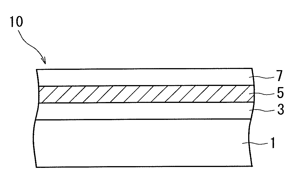
[0075]Next, the ink for laser marking was printed on a 12 μm-thick protection layer of polyethylene terephthalate and was dried to form an ink layer and on which was formed a 3 μm-thick underlying layer of urethane resin containing titanium oxide that was a white inorganic pigment. Thereafter, a 70 μm-thick base film of polypropylene was stuck thereto via an adhesive, and the thus obtained film was irradiated with a laser beam from...

experimental example 2

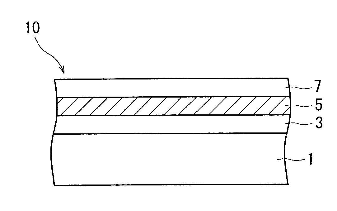
[0077]A film was prepared in the same manner as in Experimental Example 1 but without adding the titanium oxide that was the white inorganic pigment to the ink for laser marking and without forming the underlying layer. The film was irradiated with the laser beam and was evaluated in the same manner as in Experimental Example 1.


PUM

PropertyMeasurementUnit
wavelengthaaaaaaaaaa
particle diameter D50aaaaaaaaaa
thicknessaaaaaaaaaa

Abstract

To provide a laser-marking film having a laser-marking ink layer capable of forming vivid images when it is irradiated with a laser beam for forming laser markings. A laser-marking film comprising a base film 1, a white underlying layer 3 formed on the base film 1, and an ink layer 5 for laser marking formed on the underlying layer 3, wherein the ink layer 5 contains, dispersed therein, an iron oxide as a laser beam-absorbing agent in an amount of 0.1 to 30 parts by weight per 100 parts by weight of a resin binder.

Description

TECHNICAL FIELD[0001]This invention relates to a laser-marking film provided with an ink layer capable of forming markings by the irradiation with a laser beam.BACKGROUND ART[0002]So far, the product data such as a variety of distribution data (date of production, eat-by freshness date, etc.) and product management data (serial number, etc.) have been printed on the industrial products in the form of line images such as bar codes and characters.[0003]As the systems for printing the above product data, there have, generally, been known a thermal transfer system, an ink jet system and a laser system. Among them, however, the printing system based on the laser beam has now been widely employed. Namely, according to the laser system, a layer blended with a laser beam-absorbing agent and for forming laser markings is irradiated with a laser beam, and the surrounding resin is carbonized by the heat generated by the laser beam-absorbing agent to thereby form a black image. According to thi...

Claims


Application Information

Patent Timeline
Patent Type & Authority Patents(United States)
IPC IPC(8): B41M5/00B41M5/10B41M5/52C23C30/00F01D5/28G03G7/00
CPCB41M5/26B41M5/10H04N1/00127G03G7/0013F01D5/288C23C30/00B41M5/5254B41M5/5218E04H6/422H01M10/44H02J7/0027Y10T428/257Y10S428/9133Y10T428/24901Y10T428/24893B41M7/0027Y02E60/10B41M5/502B41M5/52
Inventor FUKUE, KEIJIFUKAHORI, ATSUSHISUGIYAMA, MACHIKOTANAKA, SHINJIMATSUSHIMA, JUN
Owner TOYO SEIKAN KAISHA LTD
Why Eureka
Try Eureka