Flip chip interconnection system having solder position control mechanism
a technology of position control mechanism and flip chip, which is applied in the direction of printed circuit manufacturing, printed circuit aspects, conductive material removal by irradiation, etc., can solve the problems of inconvenient design of solder mask openings that only leave wettable pads exposed, inconvenient connection of solder bumps, and long time-consuming for those skilled in the art to solv
- Summary
- Abstract
- Description
- Claims
- Application Information
AI Technical Summary
Benefits of technology
Problems solved by technology
Method used
Image
Examples
first embodiment
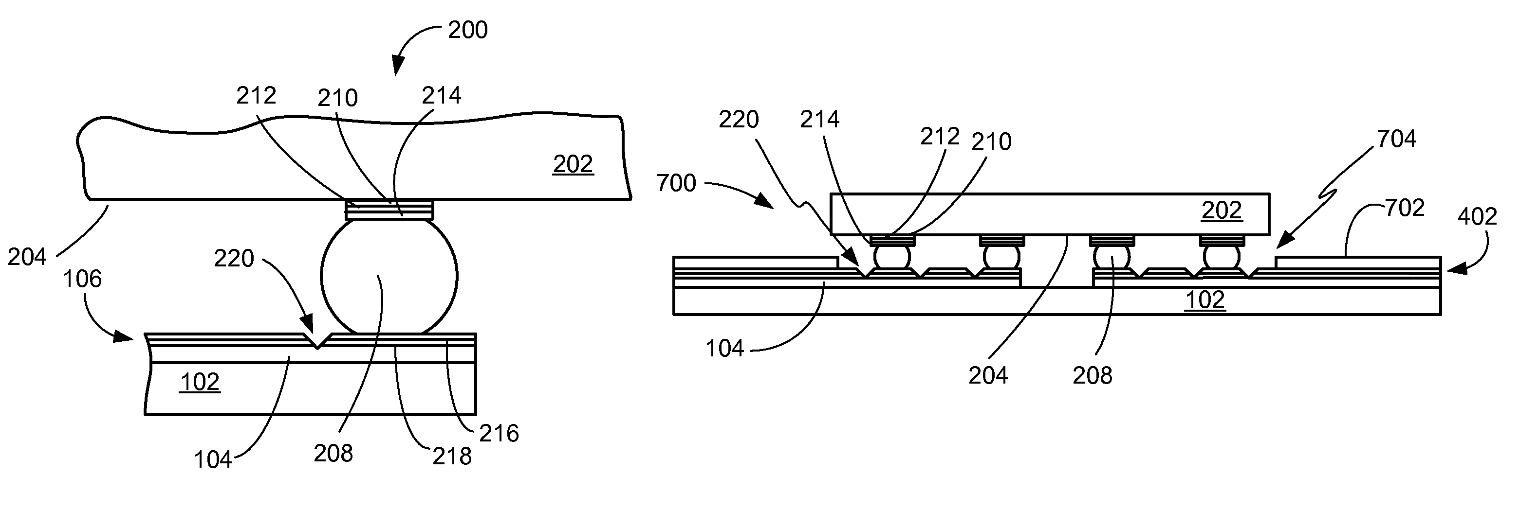
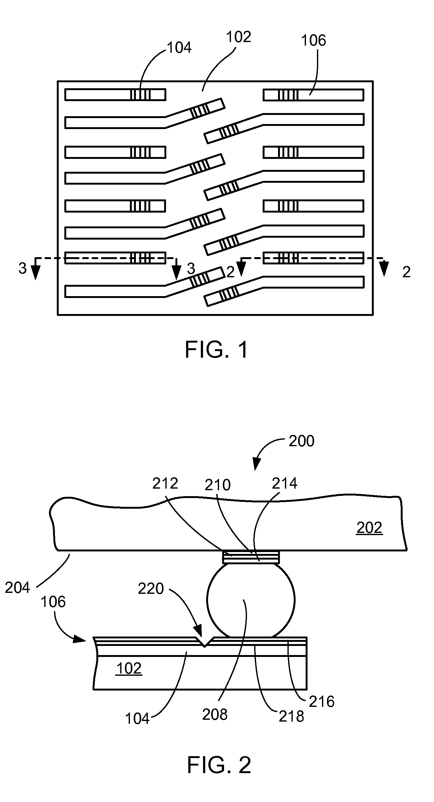
[0039]Referring now to FIG. 2, therein is shown a close up of a cross-sectional view of a flip chip interconnection system 200 along line 2-2 of FIG. 1 in the present invention.
[0040]The flip chip interconnection system 200 includes a flip chip 202 having an active side 204, a conductive bump 208, such as a solderable conductive interconnect, the substrate 102 with the conductive trace 104, and the protective coating 106.
[0041]The flip chip 202 may be electrically and mechanically coupled to the substrate 102 using a flip chip interconnect, such as the conductive bump 208. The conductive bump 208 can be of solder materials such as lead, tin, and antimony.
[0042]To attach the conductive bump 208 to the flip chip 202, an under bump metallization is applied on the flip chip 202. The under bump metallization consists of an adhesion layer 210, such as titanium tungsten, for good adhesion to the flip chip 202, a barrier layer 212, such as a gold, to limit the diffusion of solder into the u...
second embodiment
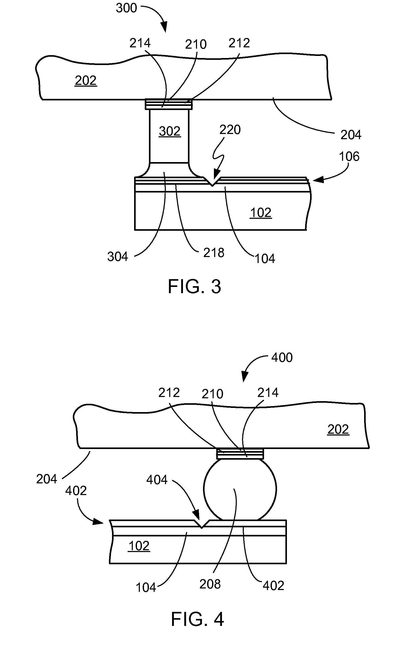
[0048]Referring now to FIG. 3, therein is shown a close up of a cross-sectional view of a flip chip interconnection system 300 along line 2-2 of FIG. 1 in the present invention.
[0049]The flip chip interconnection system 300 includes the flip chip 202 having the active side 204, conductive pillars 302, and the substrate 102 with the conductive trace 104 and the protective coating 106.
[0050]The flip chip 202 may be electrically and mechanically coupled to the substrate 102 using a flip chip interconnect, such as a conductive pillar 302. The conductive pillar 302 can be of a material, such as copper. However, the conductive pillar 302, when made of copper, can have intermetallic issues and have a tendency to oxidize in the presence of some alloys.
[0051]It has been found that the conductive pillar 302 should have a solder tip 304 of lead, tin, or antimony to eliminate the impact of oxidation and intermetallics that may lead to reliability issues.
[0052]The conductive pillar 302 is often ...
third embodiment
[0063]Referring now to FIG. 4, therein is shown a close up of a cross-sectional view of a flip chip interconnection system 400 similar to FIG. 2 in the present invention.
[0064]The flip chip interconnection system 400 includes the flip chip 202 having the active side 204, the conductive bump 208, the substrate 102 with the conductive trace 104 and a protective coating 402.
[0065]The flip chip 202 may be electrically and mechanically coupled to the substrate 102 using a flip chip interconnect, such as the conductive bump 208. The conductive bump 208 can be of solder materials such as lead, tin, and antimony.
[0066]To attach the conductive bump 208 to the flip chip 202, an under bump metallization is applied on the flip chip 202. The under bump metallization consists of the adhesion layer 210, such as titanium tungsten, for good adhesion to the flip chip 202, the barrier layer 212, such as a gold, to limit the diffusion of solder into the underlying material, and the solder wettable laye...
PUM
 Abstract
Description
Claims
Application Information
 - R&D
- Intellectual Property
- Life Sciences
- Materials
- Tech Scout
- Unparalleled Data Quality
- Higher Quality Content
- 60% Fewer Hallucinations
Browse by: Latest US Patents, China's latest patents, Technical Efficacy Thesaurus, Application Domain, Technology Topic, Popular Technical Reports.
© 2025 PatSnap. All rights reserved.Legal|Privacy policy|Modern Slavery Act Transparency Statement|Sitemap|About US| Contact US: help@patsnap.com


