Finger control and data entry device

Active Publication Date: 2013-12-10
ROCKWELL COLLINS INC
View PDF6 Cites 28 Cited by
  • Summary
  • Abstract
  • Description
  • Claims
  • Application Information

AI Technical Summary

Benefits of technology

[0015]In one embodiment, the present invention provides selection of controls such as contact-required buttons and a touch strip in a compact but usable manner, suitable for access by a single finger. In a wireless implementation the device can be made further useful by retaining its placement directly on the hand/finger continuously, increasing its availability. With the addition of haptic/tactile output response sensors such as tactile buzzers, the capability to provide contact-based output to the user further extends the capability of this control device. The present invention therefore operates as a very compact (preferably single) finger-based control input device with tactile output capability in wired or wireless fashion.
[0016]The present invention's selection of contact-required (alternatives include press to hold action) buttons and touch strip provides a wide selection of control function through customizable capability assignment of each control element and their combination. When used jointly with an appropriately tailorable end system, the interface ca

Problems solved by technology

The rise of electronic device/system development and use by individuals often incurs issues in how one can control such devices in specific configurations or when performing certain actions or movements.
Similarly, data entry can be difficult to perform efficiently, often limited to keyboard-based hand-entry solutions that may not be appropriate for specific users.
One example: For the case of a dismounted soldier (in which the growth of wearable soldier computing and sensing systems is increasing), an added difficulty is the common requirement to engage a constant offensive posture by carrying a weapon (often rifle).
In this posture, the user cannot typically utilize keyboard or other hand based controller solutions common to several devices.
None of the aforementioned devices provide a holistic solution to addressing the specific dependencies of the high stress, minimalist, non-commercial workspace or non-gaming b

Method used


Image

  • Finger control and data entry device
  • Finger control and data entry device
  • Finger control and data entry device

Examples


first embodiment

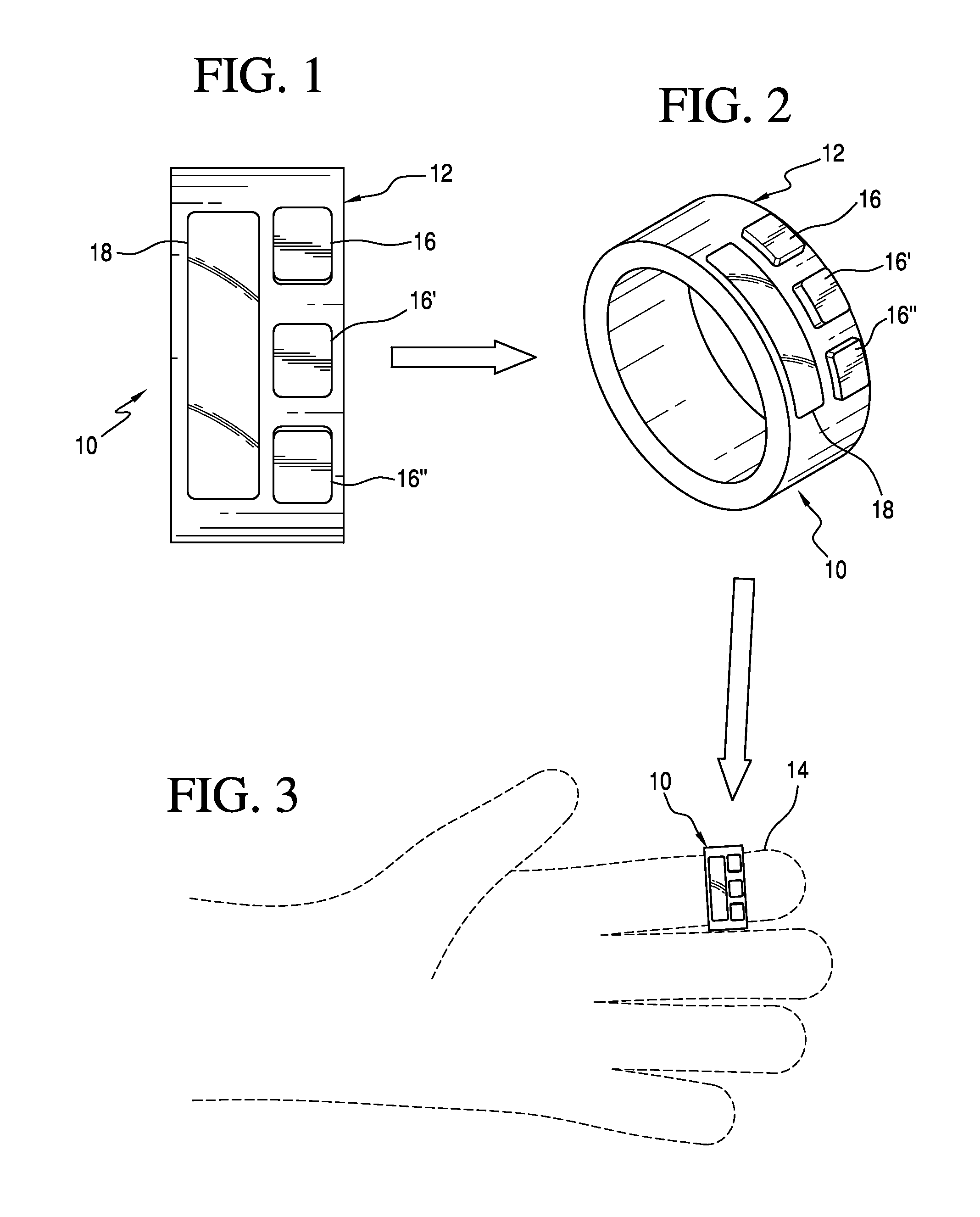
[0028]Referring now to the drawings and the characters of reference marked thereon, FIGS. 1-3 illustrate the finger control and data entry device of the present invention, designated generally as 10. The device 10 includes a retaining element, designated generally as 12, adapted to fit on a single finger 14 of an operator. The retaining element 12 has an outer mounting surface thereon. A plurality of pushbuttons 16, 16′, 16″ are mounted on the mounting surface. A touch strip 18 is mounted on the mounting surface. For this single finger implementation the retaining element comprises a ring element. The retaining element 12 may be formed of, for example, rigid or flexible material depending on the preferred manifestation of the device. A combination of both enables an electronics casing and flexible mounting approach. Retention approaches can be utilized using hook and loop fasteners, a buckle, or other means.

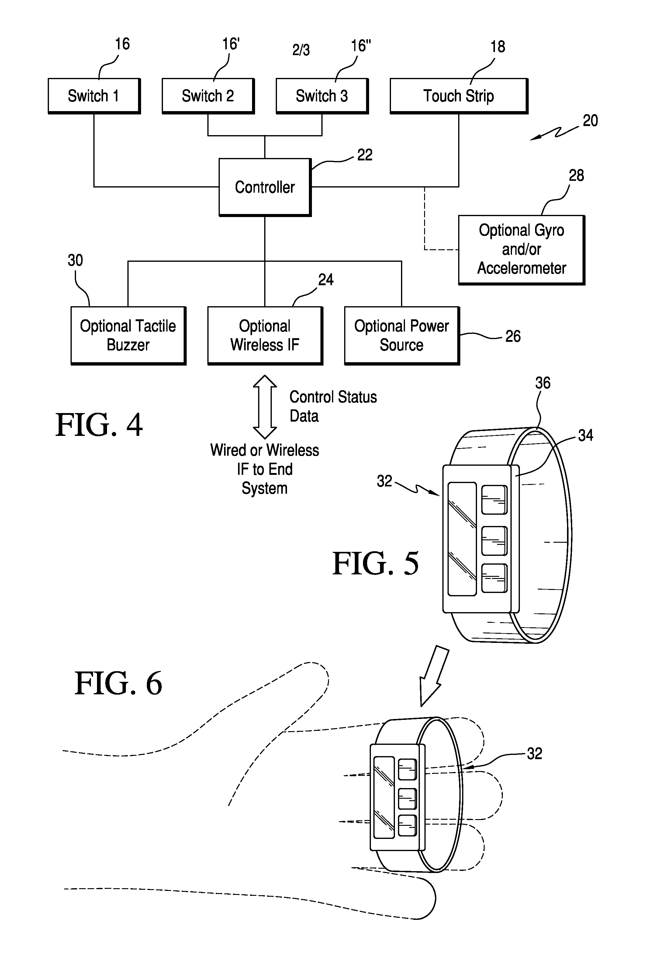
[0029]Referring now to FIG. 4, a functional system block diagram of the pres...

second embodiment

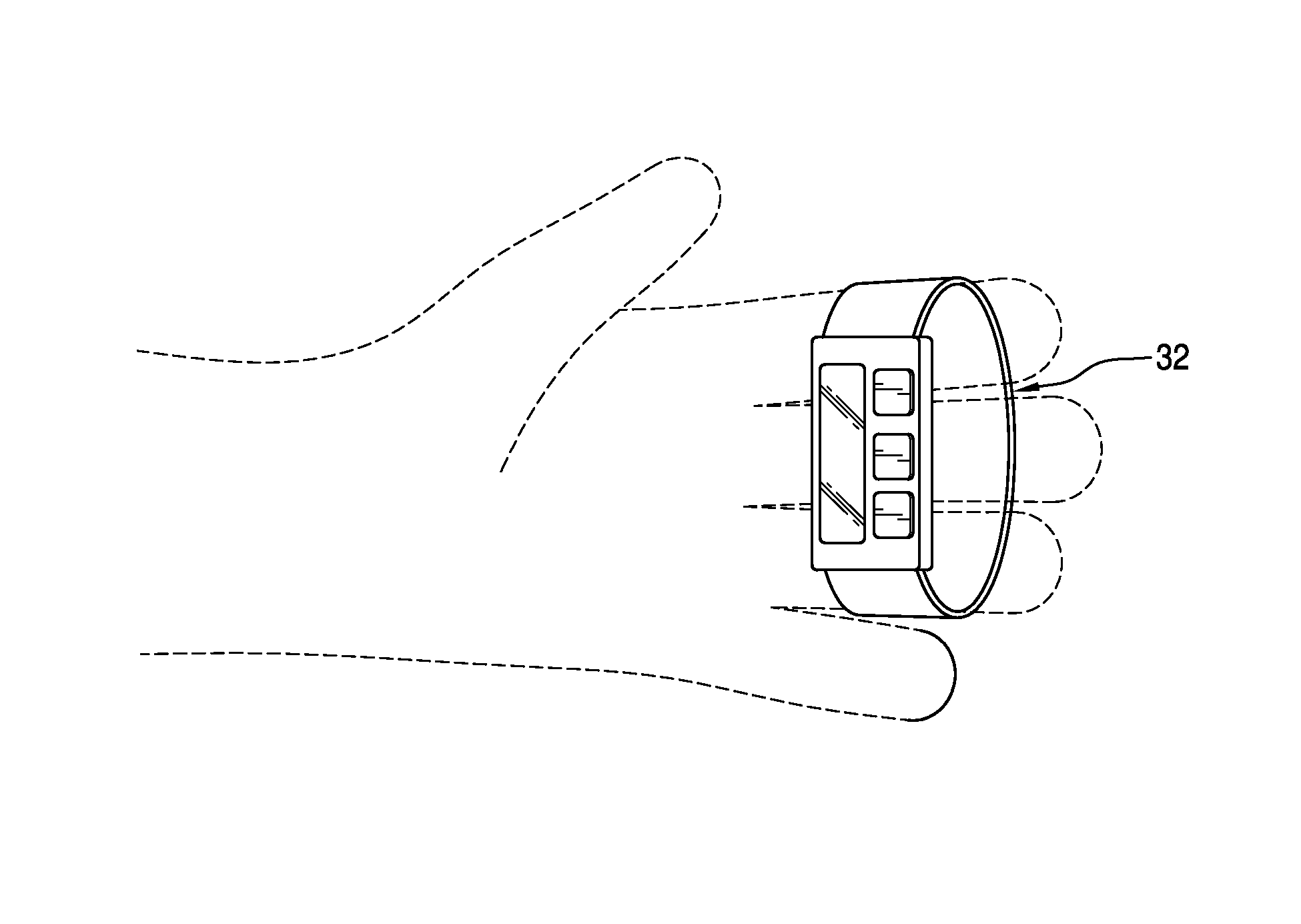
[0038]Referring now to FIGS. 5 and 6, the device utilized on three fingers of the operator, is illustrated, designated generally as 32. As shown, in FIG. 5, the electro / mechanical components of the device 32 may be mounted on a rigid support structure 33 if a flexible retaining element 36 is utilized. An additional manifestation utilizing only flexible support structure elements may also be foreseen to encase the device's functional elements.

[0039]The ability to enable a flexibly adjustable retention approach to the case or mounting structure may also be applied. Referring to FIG. 7, an adjustable device is illustrated, designated generally as 38, where the retaining element 40 includes VELCRO® hook and fastener means 42, 44. Referring now to FIG. 8, another adjustable device is illustrated, designated generally as 46, where the retaining element 48 includes flexible material 50 and an adjustable buckle or snap mechanism 52, 54.

[0040]In use, a user may locate the device on a finger ...


PUM


Abstract

A finger control and data entry device that includes a retaining element adapted to fit on at least one finger of an operator. The retaining element has an outer mounting surface thereon. Pushbuttons are mounted on the mounting surface. A touch strip is mounted on the mounting surface. A controller is operably connected to the pushbuttons and the touch strip for the interface handling of a communications link. A communications link is operably connected to the controller to provide an output signal for use by an end system. Power is provided to the controller. Utilization of the pushbuttons in combination with the touch strip on the retaining element provides a finger-based system control. The inclusion of vibrating sensors within the device enables a direct means of information and/or status feedback.

Description

BACKGROUND OF THE INVENTION[0001]1. Field of the Invention[0002]The present invention relates generally to device controllers, and more particularly to a compact finger-based control input device.[0003]2. Description of the Related Art[0004]The rise of electronic device / system development and use by individuals often incurs issues in how one can control such devices in specific configurations or when performing certain actions or movements. Similarly, data entry can be difficult to perform efficiently, often limited to keyboard-based hand-entry solutions that may not be appropriate for specific users. One example: For the case of a dismounted soldier (in which the growth of wearable soldier computing and sensing systems is increasing), an added difficulty is the common requirement to engage a constant offensive posture by carrying a weapon (often rifle). In this posture, the user cannot typically utilize keyboard or other hand based controller solutions common to several devices.[00...

Claims


Application Information

Patent Timeline
IPC IPC(8): G09G5/00
CPCG06F3/014G06F3/0346G06F3/03547G06F3/03545G06F2203/0384
Inventor KELLY, JOHN T.
Owner ROCKWELL COLLINS INC
Why Eureka
Try Eureka