Ignition device for a laser ignition of an internal combustion engine

a laser ignition and internal combustion engine technology, applied in the direction of machines/engines, spark plugs, mechanical equipment, etc., can solve the problems of clear pressure rise in the intervening space, stressing the sealing surface between the combustion chamber window and the inner sleeve of the housing, etc., to improve the service life and reliability

Inactive Publication Date: 2013-12-17
ROBERT BOSCH GMBH
View PDF11 Cites 7 Cited by
  • Summary
  • Abstract
  • Description
  • Claims
  • Application Information

AI Technical Summary

Benefits of technology

[0008]An object of the present invention is providing an ignition laser having an additionally improved service life and reliability.
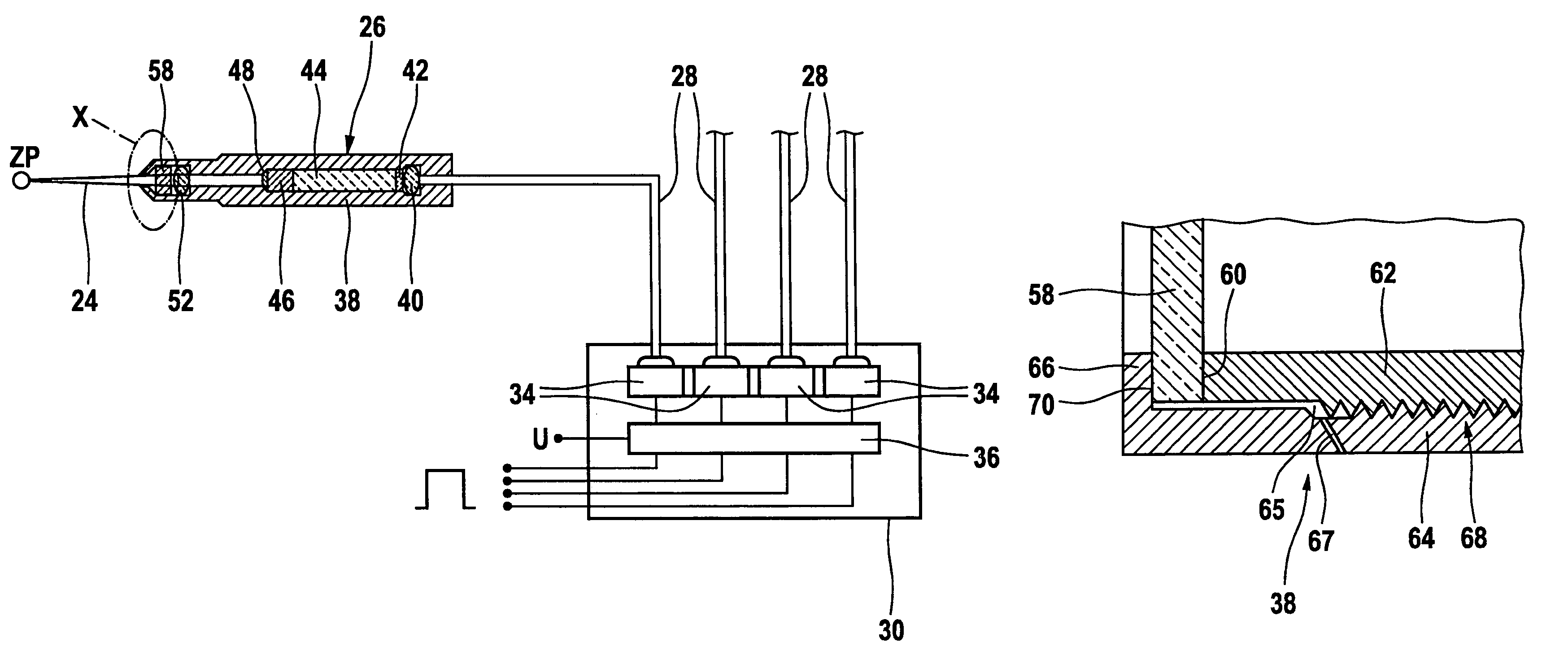
[0010]The pressure-equalization device according to the present invention is intended, so to speak, as a backup system for the sealing concept of the laser ignition device. For if, during operation of the laser ignition device, only minimal leakages should occur, this may lead to the pressure in the intervening space rising clearly above the environmental pressure, and as a result greatly stressing the sealing surface between the combustion chamber window and the inner sleeve of the housing. It is ensured by the pressure-equalization device according to the present invention that, even at small minimum leakage flows between the outer housing and the combustion chamber window, the sealing surface between the combustion chamber window and the inner sleeve is not stressed in an inadmissible manner, so that the inside of the housing is protected reliably from combustion gases and the pollutants contained in the combustion gases.
[0011]Because of the pressure-equalization device according to the present invention, the sealing of the inside of the housing is still maintained even if the first-mentioned sealing surface, which is, in the nature of things, exposed to higher thermal and chemicals stresses, should begin to leak in the course of operating duration of the internal combustion engine, or of the laser ignition device. Because of the pressure-equalization device according to the present invention, an exhaust gas quantity, flowing into the intervening space between the outer sleeve and the combustion chamber window, based on a leakiness, is able to be carried off. As a result, the pressure in the intervening space does not rise, and the operating conditions of the second seal between the combustion chamber window and the inner sleeve do not change. An inadmissible pressure application to the intervening space is also avoided.
[0015]A further advantageous embodiment of the present invention provides closing the pressure-equalization bore by a stopper made of a curable plastic, for instance, which takes over the function of a seal. An especially suitable material is polyimide, based on its high temperature stability. One additional suitable material is silicone, based on its high gas permeability, but being impermeable to particles and liquids.
[0016]By closing the pressure-equalization bore using a stopper, it is first of all ensured that, in normal operation, i.e. when the seal between outer sleeve and combustion chamber window is completely tight, the pressure-equalization bore is closed, and consequently, no contamination is able to get into the intervening space. If, however, the pressure in the intervening space rises, for instance, to 4 bar above the environmental pressure, the stopper is squeezed out of the pressure-equalization bore by these pressure forces, and the pressure-equalization bore makes possible a pressure equalization between the intervening space and the environment. This assures that no inadmissibly high pressures are able to occur in the intervening space.

Problems solved by technology

For if, during operation of the laser ignition device, only minimal leakages should occur, this may lead to the pressure in the intervening space rising clearly above the environmental pressure, and as a result greatly stressing the sealing surface between the combustion chamber window and the inner sleeve of the housing.

Method used


Image

  • Ignition device for a laser ignition of an internal combustion engine
  • Ignition device for a laser ignition of an internal combustion engine
  • Ignition device for a laser ignition of an internal combustion engine

Examples


Embodiment Construction

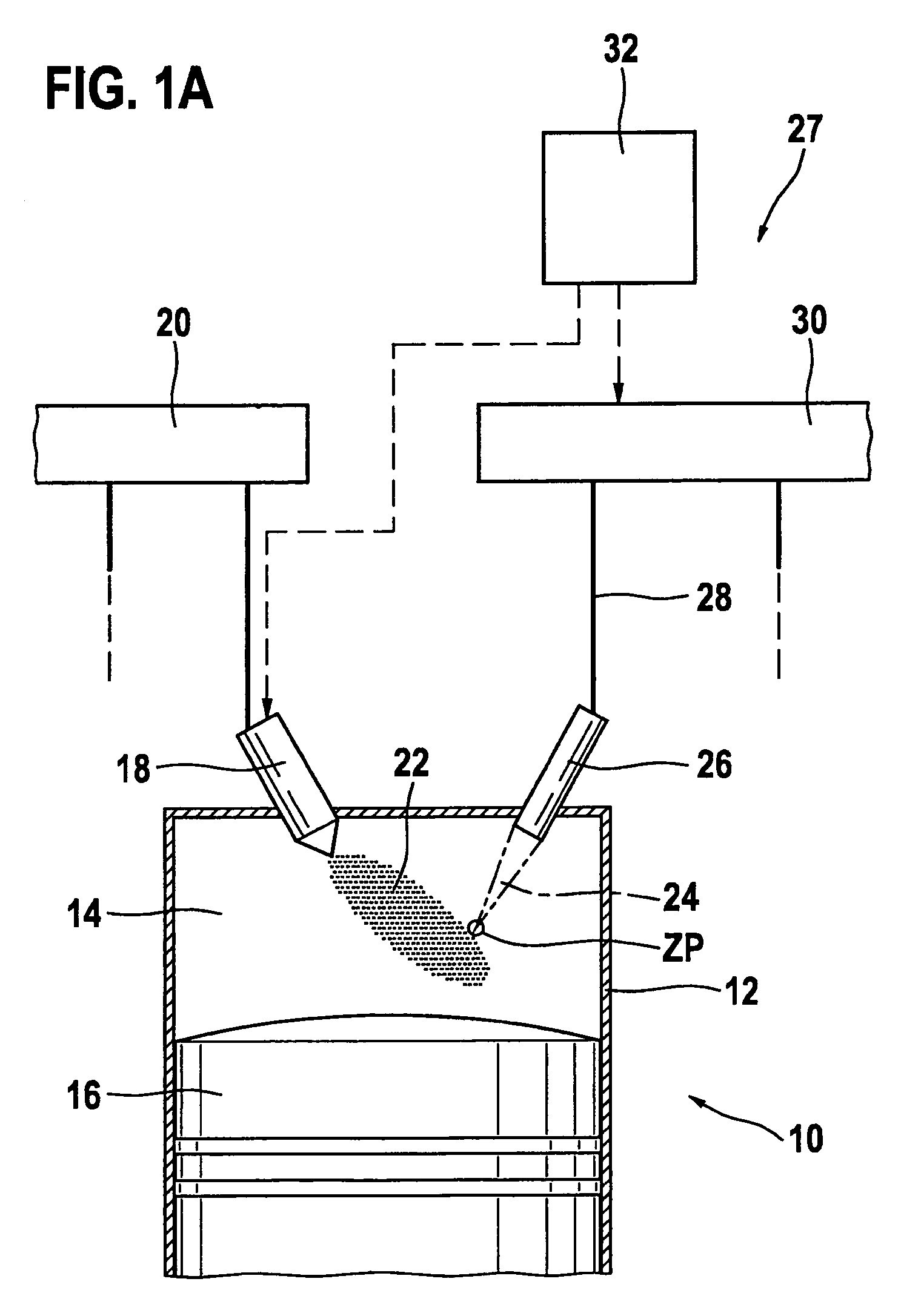
[0022]In FIG. 1a, the entire internal combustion engine is denoted by reference numeral 10. It may be used for driving a motor vehicle that is not shown. Internal combustion engine 10 usually includes multiple cylinders, only one of which is designated in FIG. 1 by reference numeral 12. A combustion chamber 14 of cylinder 12 is bounded by a piston 16. Fuel reaches combustion chamber 14 directly through an injector 18, which is connected to a fuel pressure reservoir 20 that is also designated as a rail. Alternatively the fuel-air mixture may also be formed outside of combustion chamber 14, for instance, in the intake manifold.

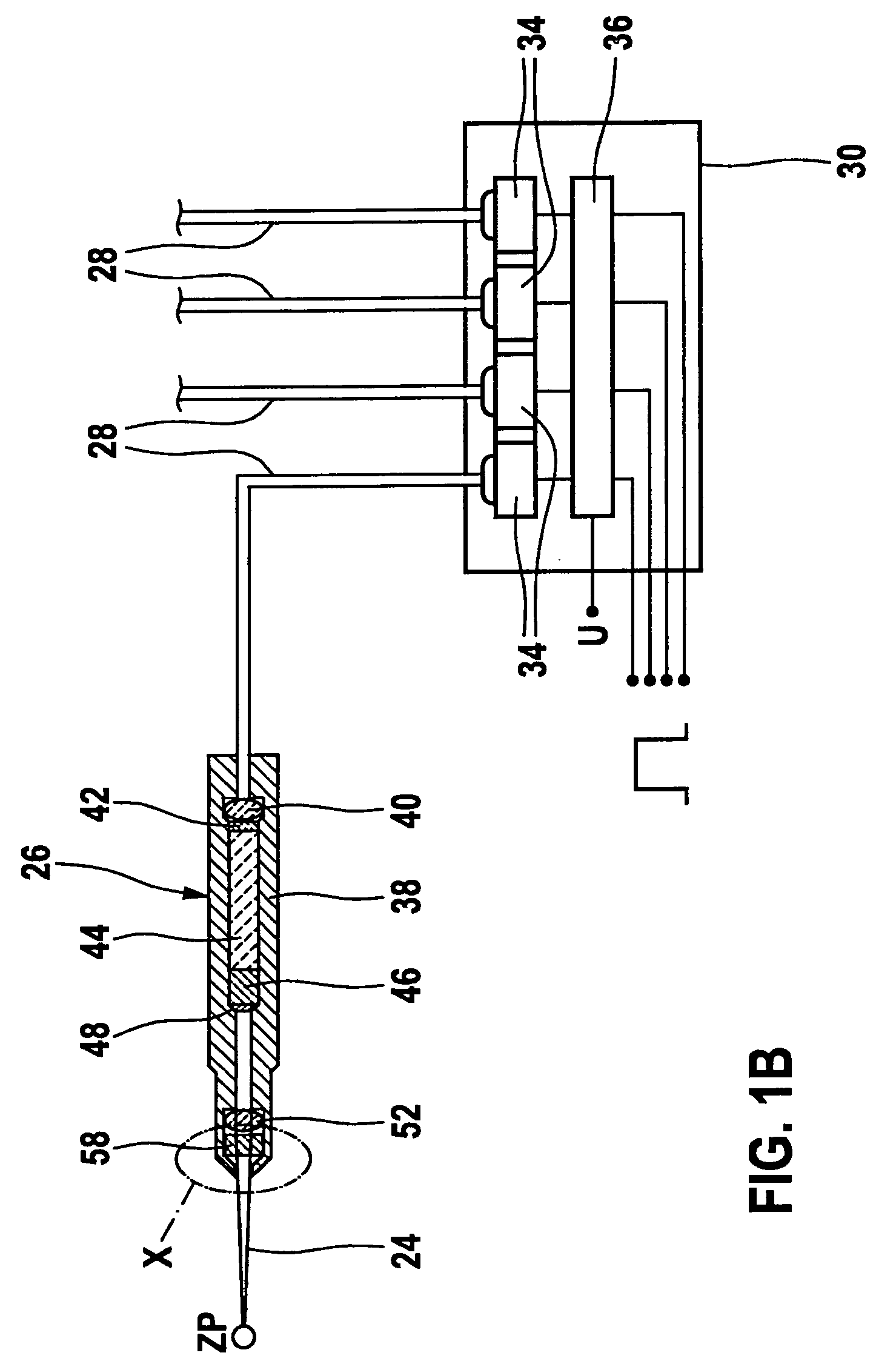
[0023]Fuel-air mixture 22 inside combustion chamber 14 is ignited by a laser pulse 24, which is radiated into combustion chamber 14 by an ignition device 27 which includes an ignition laser 26. For this purpose, laser device 24 is fed, via a light-guide device 28, with a pumping light provided by a pumping light source 30. Pumping light source 30 is controlled b...


PUM


Abstract

An ignition laser is provided for an internal combustion engine, in which the combustion chamber window is connected to a housing of the ignition laser in a gas-resistant, pressure-resistant, and temperature-resistant manner. Furthermore, a pressure relief bore is present which effectively prevents a pressure increase in the housing of the ignition laser.

Description

BACKGROUND OF THE INVENTION[0001]1. Field of the Invention[0002]The present invention relates to an ignition device for providing laser ignition of an internal combustion engine.[0003]2. Description of Related Art[0004]A so-called laser ignition is known from published international PCT patent application WO 2005 / 066488 A1. This laser ignition includes an ignition laser, which extends into the combustion chamber of an internal combustion engine. The ignition laser is optically pumped by a pumping light source via a fiber optic guide.[0005]At one end of the ignition laser facing the combustion chamber, there is a so-called combustion chamber window, which is able to transmit the laser beams generated for the ignition laser. This combustion chamber window has to be accommodated in a sealing manner in a housing of the ignition laser. There are high requirements on the sealing between the combustion chamber window and the housing, because during the operation of the internal combustion ...

Claims


Application Information

Patent Timeline
Patent Type & Authority Patents(United States)
IPC IPC(8): F02P23/04F02P23/00
CPCF02C7/264F02P23/04
Inventor WEINROTTER, MARTINWOERNER, PASCALRAIMANN, JUERGENWOLZ, DIETER
Owner ROBERT BOSCH GMBH
Why Eureka
Try Eureka