Methods for applying energy to tissue using a graphical interface

a graphical interface and tissue technology, applied in the field of tissue energy application, can solve the problems of skin sagging, wrinkles, and other undesirable distortions, and achieve the effect of preventing energy from affecting the outer layer of skin and improving appearan

Active Publication Date: 2013-12-17
SYNERON MEDICAL LTD
View PDF21 Cites 31 Cited by
  • Summary
  • Abstract
  • Description
  • Claims
  • Application Information

AI Technical Summary

Benefits of technology

[0015]The invention provides improved systems and methods of percutaneously delivering energy to tissue where the systems and methods enable a physician (or other medical practitioner) to precisely control the areas or region of tissue that receives energy. In one aspect of the invention, the methods and systems produce cosmetically beneficial effects of using energy to shrink collagen tissue in the dermis in an effective manner that prevents the energy from affecting the outer layer of skin. However, the devices and method described herein can target the underlying layer of adipose tissue or fat for lipolysis or the breakdown of fat cells. Selecting probes having sufficient length to reach the subcutaneous fat layer allows for such probes to apply energy in the subcutaneous fat layer. Application of the energy can break down the fat cells in that layer allowing the body to absorb the resulting free fatty acids into the blood stream. Such a process can allow for contouring of the body surface for improved appearance. Naturally, such an approach can be used in the reduction of cellulite. In addition, the systems and methods are also useful for treating other skin surface imperfections and blemishes by application of a percutaneous treatment.
[0016]The devices described herein generally include energy delivery devices for delivering energy from an energy supply unit to a target region beneath a surface of tissue. The system also includes features that improve delivery of the probes delivering the energy within specific layers of tissue.
[0027]The stabilization plate can also include a cooling source coupled thereto, such that the stabilization plate maintains a temperature at, below, or slightly above body temperature. In some variation, the cooling source can include one or more heat pipes that permit placement of at least a portion of the cooling source towards a proximal end of the device body. This permits spacing of the cooling source from the stabilization plate to prevent visual interference of the stabilization plate.
[0035]In certain variations, the controller of the system can prevents energy delivery to the probe when the tissue parameter is less than 250 ohms or greater than 3000 ohms. When the impedance is between 300 and 1500 ohms the controller can provide energy at a first set of parameters, and when the tissue parameter is between 1500 and 3000 ohms the controller can provide energy at a second set of parameters to account for the varying tissue.
[0037]The system can also include various safety measures to prevent undesired damage to tissue. For example, the system can stop application of energy if a parameter measured by the probes exceeds a pre-determined value or range of values. Such a measured parameter can include one or more parameters including applied energy, a tissue temperature, an electrical impedance, an applied power, an applied voltage, and an applied current. Some examples of the pre-determined values include limiting energy delivery to between 2 and 4 joules, limiting temperature to not to exceed the target temperature by between 5 and 20%; and ensuring that the electrical impedance of the tissue is between 250 and 3000 ohms.

Problems solved by technology

Exposure of the skin to environmental forces can, over time, cause the skin to sag, wrinkle, form lines, or develop other undesirable distortions.
These and other effects of the normal aging process can present an aesthetically unpleasing cosmetic appearance.
Still, laser or chemical resurfacing leads to prolonged redness of the skin, infection risk, increased or decreased pigmentation, and scarring.
In one example, fabrication of an electrode array may cause undesired cross-current paths forming between adjacent electrodes resulting in an increase in the amount of energy applied to tissue.
In such systems that treat in a non-invasive manner, generation of energy to produce a result at the dermis results in unwanted energy passing to the epidermis and subcutaneous layers.
Accordingly, excessive energy production creates the risk of unwanted collateral damage to the skin.

Method used


Image

  • Methods for applying energy to tissue using a graphical interface
  • Methods for applying energy to tissue using a graphical interface
  • Methods for applying energy to tissue using a graphical interface

Examples


Embodiment Construction

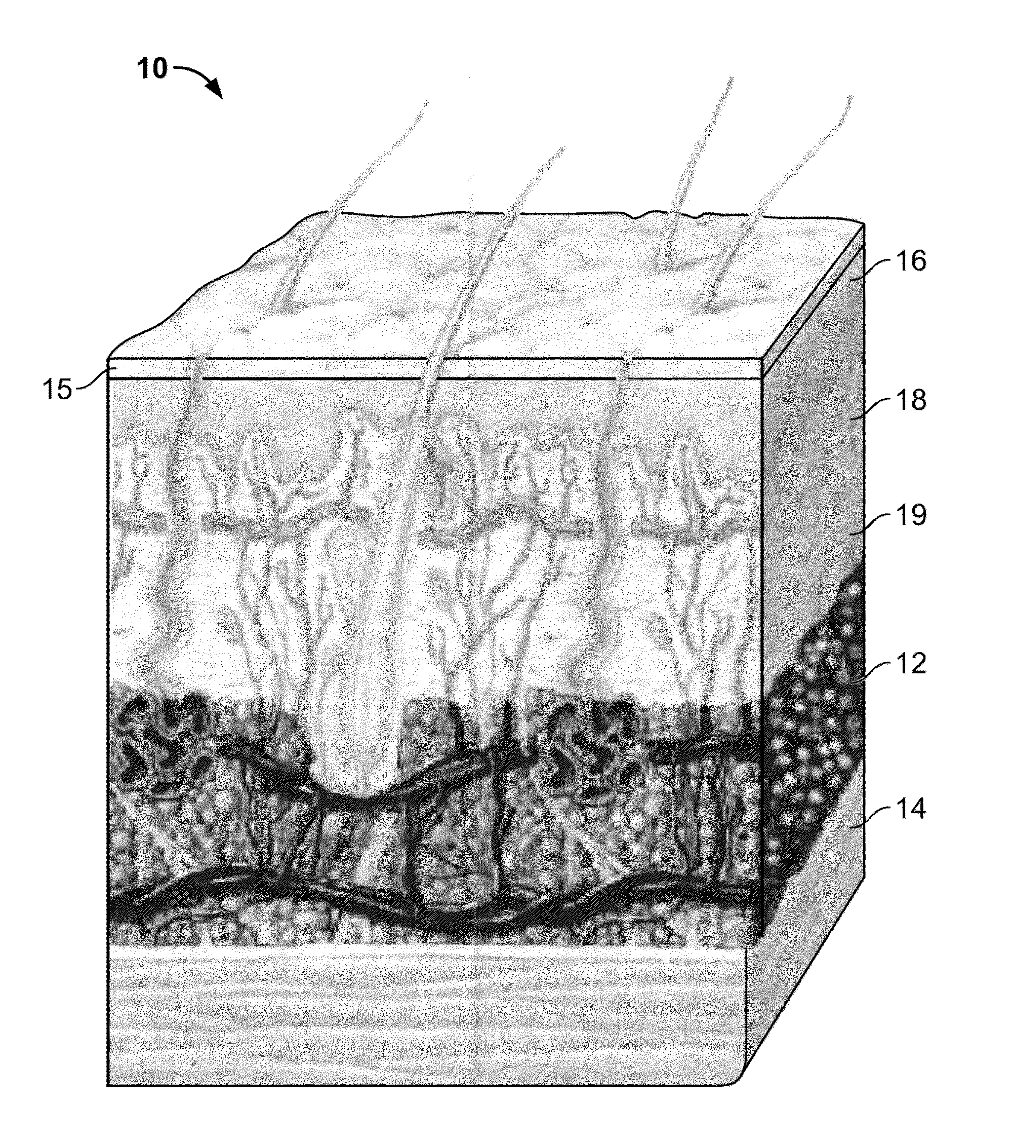
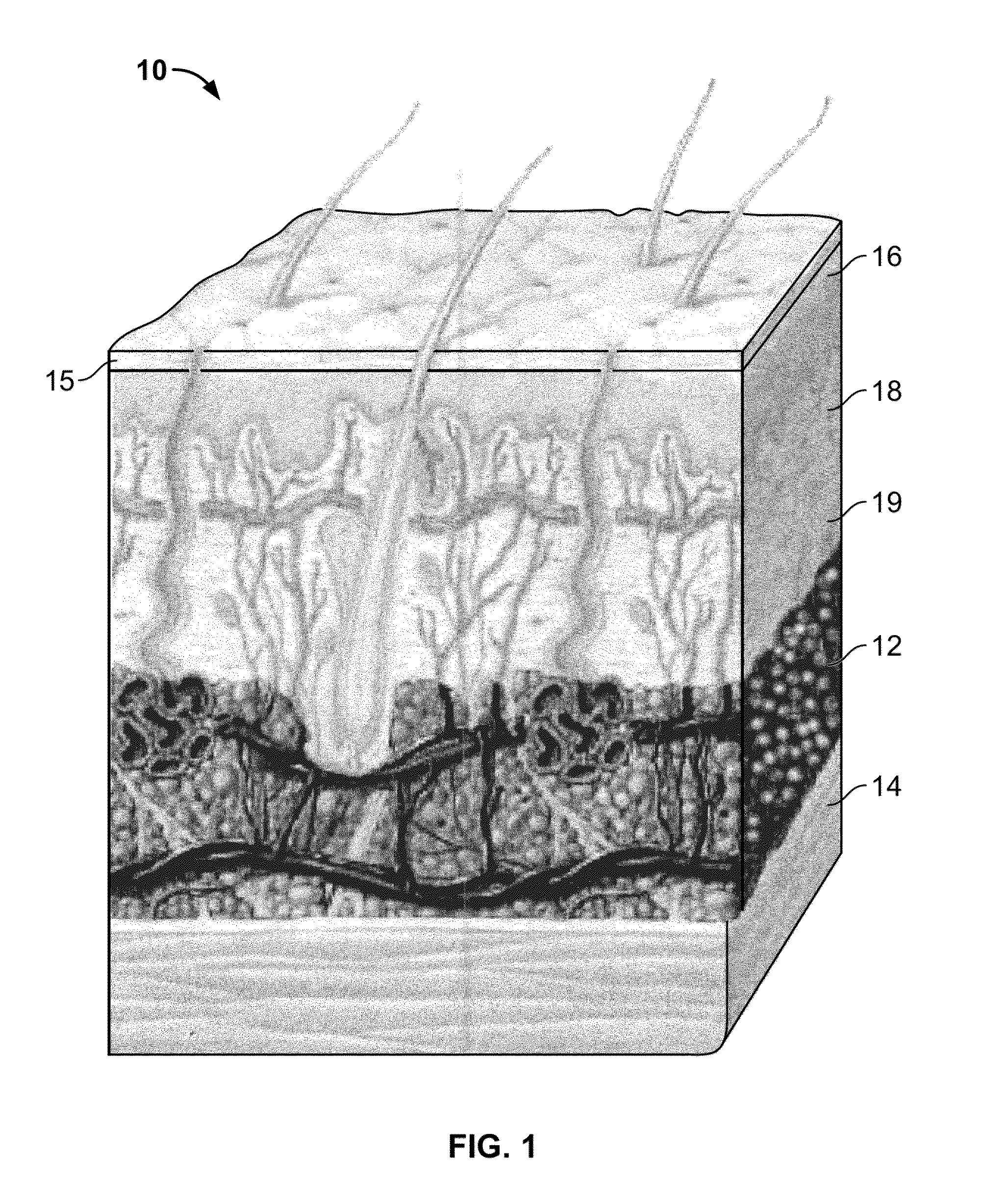
[0074]The systems and method discussed herein treat tissue in the human body. In one variation, the systems and methods treat cosmetic conditions affecting the skin of various body parts, including face, neck, and other areas traditionally prone to wrinkling, lines, sagging and other distortions of the skin. The methods and systems described herein may also have application in other surgical fields apart from cosmetic applications.

[0075]The inventive device and methods also include treatment of skin anomalies such as warts (Verruca plana, Verruca vulgaris), sebaceous hyperplasia or acne (Acne vulgaris). Treatment of acne can be accomplished by the direct ablation of sebaceous glands or it can be accomplished by the delivery of thermal energy which will stimulate the body's immune system to eliminate the bacteria, Propionibacterium acnes, which is one of the causes of acne. The methods and devices can be used for the removal of unwanted hair (i.e., depilation) by applying energy or h...


PUM


Abstract

The invention provides a system and method for percutaneous energy delivery in an effective, manner using one or more probes. Additional variations of the system include array of probes configured to minimize the energy required to produce the desired effect.

Description

CROSS-REFERENCE[0001]This application is a continuation of U.S. patent application Ser. No. 12 / 367,448 filed on Feb. 6, 2009 entitled DEVICES AND METHODS FOR PERCUTANEOUS ENERGY DELIVERY, the entirety of which is incorporated by reference.BACKGROUND OF THE INVENTION[0002]The systems and method discussed herein treat tissue in the human body. In a particular variation, systems and methods described below treat cosmetic conditions affecting the skin of various body parts, including face, neck, and other areas traditionally prone to wrinkling, lines, sagging and other distortions of the skin.[0003]Exposure of the skin to environmental forces can, over time, cause the skin to sag, wrinkle, form lines, or develop other undesirable distortions. Even normal contraction of facial and neck muscles, e.g. by frowning or squinting, can also over time form furrows or bands in the face and neck region. These and other effects of the normal aging process can present an aesthetically unpleasing cos...

Claims


Application Information

Patent Timeline
Patent Type & Authority Patents(United States)
IPC IPC(8): A61B18/18A61F7/00A61F7/12
CPCA61B18/1206A61B2018/00767A61B19/56A61B2017/00084A61B2018/00005A61B2018/0016A61B2018/00678A61B2018/00791A61B2018/00875A61B2018/1425A61B2018/143A61B2018/1475A61B2018/208A61B2019/5276A61N7/00A61B2018/00452A61B2018/00994A61B2018/00642A61B18/1477A61B34/25A61B2090/378
Inventor MEHTA, BANKIM H.MCGILL, SCOTT A.BORDON, DARYL
Owner SYNERON MEDICAL LTD
Why Eureka
Try Eureka