Switchgear bus assembly having reduced power loss, material and temperature

a technology of switchgear and bus assembly, which is applied in the direction of bus-bar installations, total enclosed installations, electric cables, etc., can solve the problems of high cost of copper, poor thermal dissipation, and increased current distribution of switchgear at higher temperatures, so as to reduce the amount of conductive material required in each of multiple-phase buses, improve the uniformity of current distribution, and reduce the effect of power loss and temperatur

Active Publication Date: 2013-12-31
SCHNEIDER ELECTRIC USA INC
View PDF18 Cites 12 Cited by
  • Summary
  • Abstract
  • Description
  • Claims
  • Application Information

AI Technical Summary

Benefits of technology

[0004]Electrical switchgear typically comprises electrical switching equipment for a multi-phase electrical power distribution system, a supporting structure for a bus assembly for supplying electrical current to the switching equipment, and a plurality of spaced buses mounted on the supporting structure and connecting the switching equipment to respective phases of the multi-phase electrical power distribution system. It has been found that a unique arrangement of the multiple flat conductors in the individual buses for the different phases provides improved uniformity of current distribution, which in turn reduces power losses and temperatures. As a result, the amount of conductive material required in each of multiple phase buses is reduced for any given current rating, which in turn reduces the cost, size and weight of the bus assembly and thus of the switchgear. For example, in one embodiment, it has been found that this invention permits a 25% reduction in the amount of conductive material needed in the bus assemblies of certain switchgear designed to handle three-phase power at current ratings of 4000 amperes. The improved uniformity of current distribution also reduces “hot spots.”

Problems solved by technology

As the length of these conductors increases, the power loss dissipated across the conductors increases and the temperature of the surrounding air increases due to natural convection, resulting in poor thermal dissipation and higher temperatures in the switchgear current distribution.
In the case of flat conductors, to counteract the adverse thermal effects, multiple flat conductors are stacked together, but at the cost of an increase in the amount of expensive copper.
Because of increased conductor volume, laminated flat conductors exhibit relatively poor current distribution due to the “skin effect” phenomenon, which holds that the current density near the surface of the conductor is greater than at its core.
As a result, some portions of conductors of one phase experience uneven current distribution within the conductors composing a conducting phase.

Method used


Image

  • Switchgear bus assembly having reduced power loss, material and temperature
  • Switchgear bus assembly having reduced power loss, material and temperature
  • Switchgear bus assembly having reduced power loss, material and temperature

Examples


Embodiment Construction

[0012]Although the invention will be described in connection with certain aspects and / or embodiments, it will be understood that the invention is not limited to those particular aspects and / or embodiments. On the contrary, the invention is intended to cover all alternatives, modifications, and equivalent arrangements as may be included within the spirit and scope of the invention as defined by the appended claims.

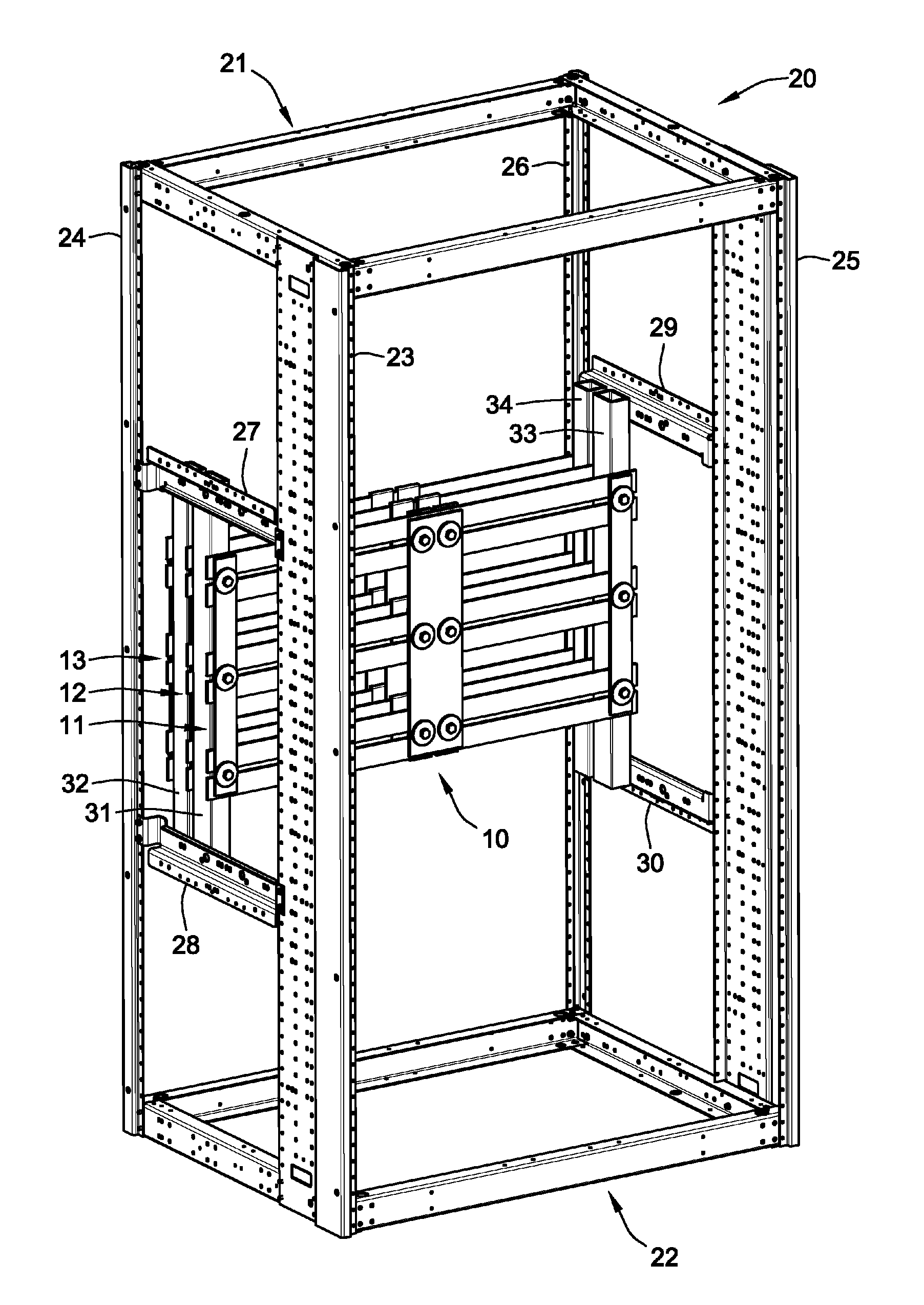
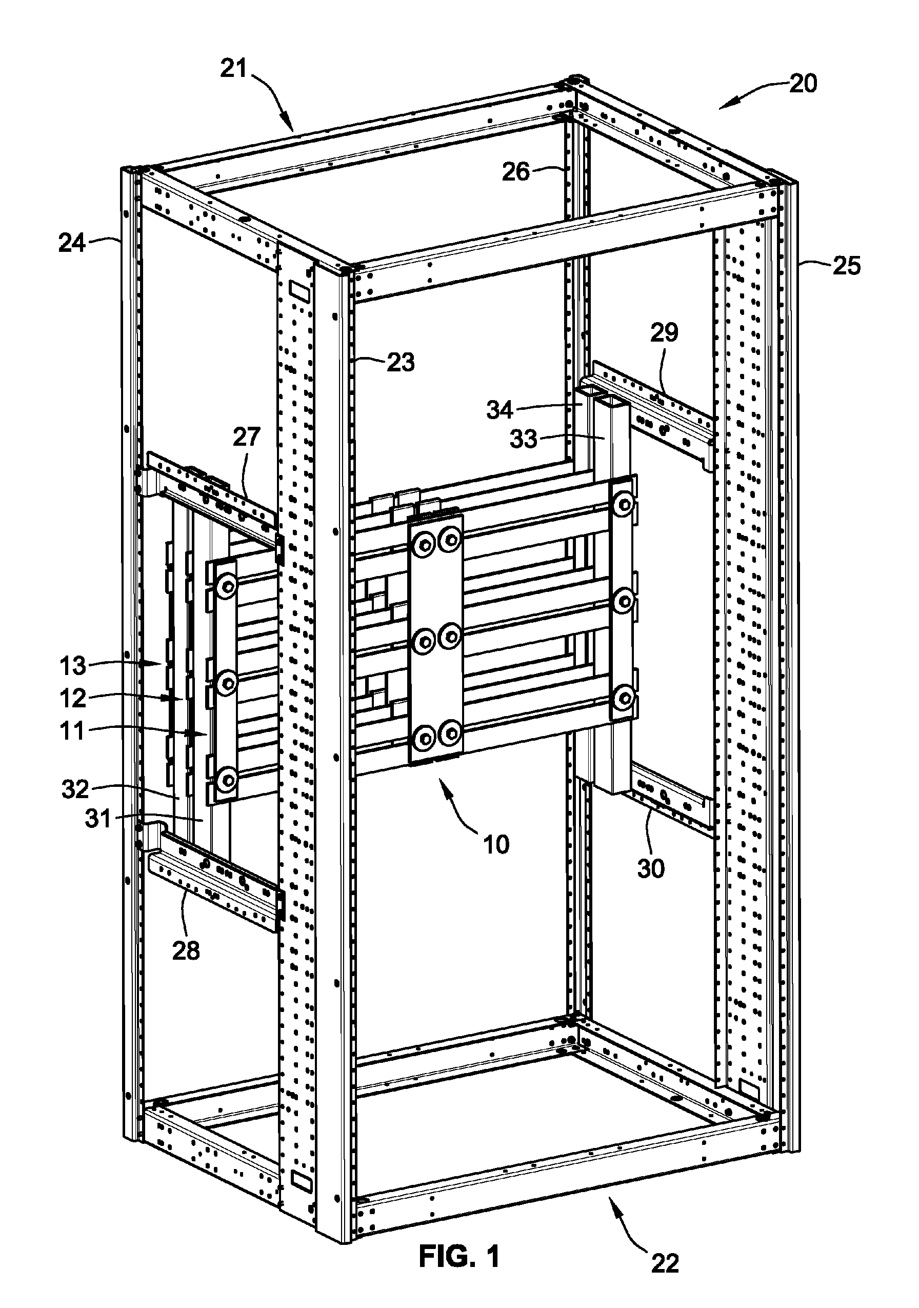
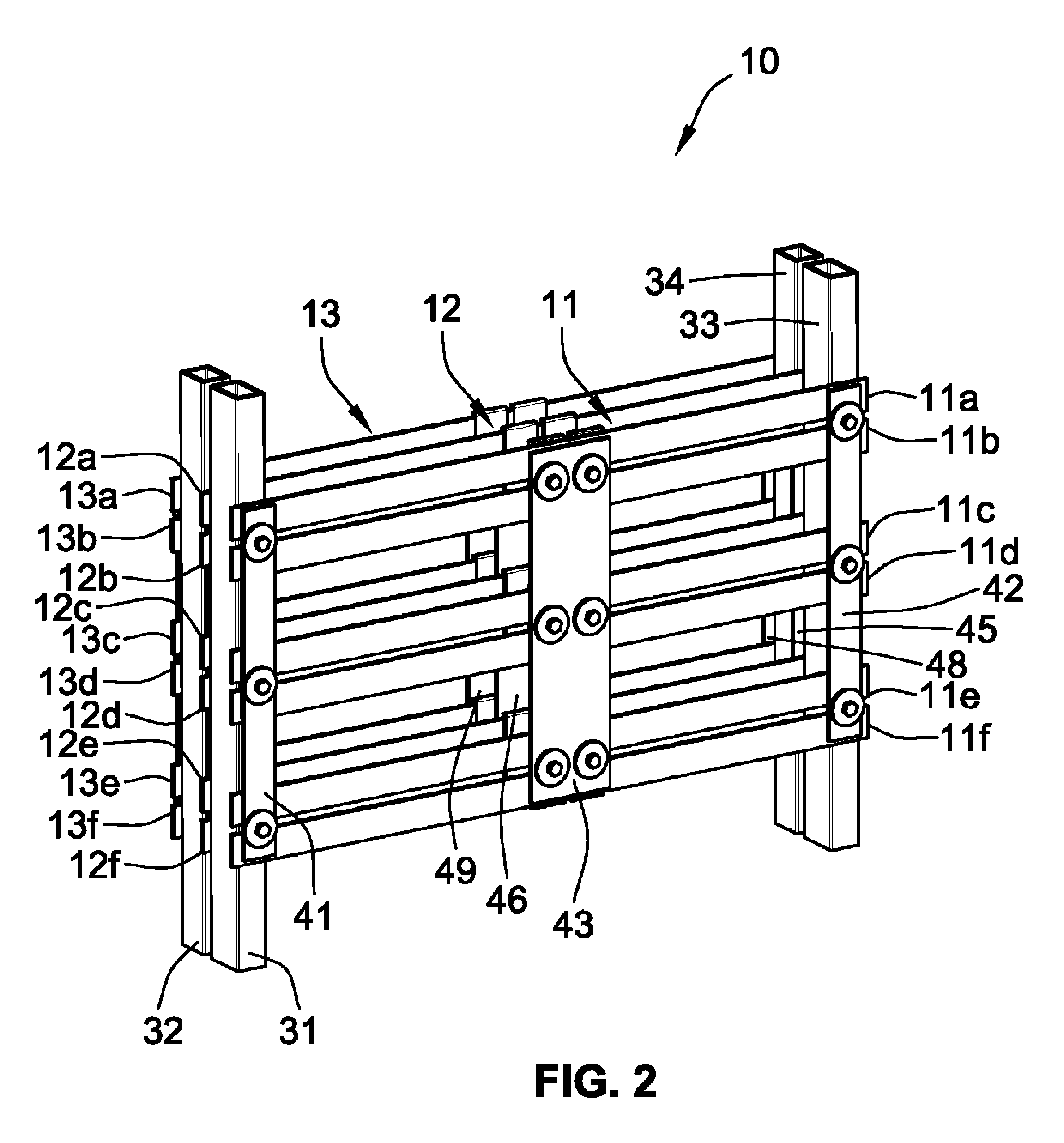
[0013]Turning now to the drawings and referring first to FIGS. 1 and 2, a bus assembly 10 for three-phase electrical distribution switchgear (not shown) includes three phase buses 11, 12 and 13, one for each of the three phases. The conductors in the buses 11-13 are made of an electrically conductive material such as copper, aluminum, etc.

[0014]The buses 11-13 are typically mounted on a supporting structure, which in the illustrative embodiment is a cage 20 that includes two horizontal rectangular end frames 21 and 22 connected to each other by four vertical corner posts 23...


PUM


Abstract

Electrical switchgear comprising electrical switching equipment for a multi-phase electrical power distribution system, a supporting structure for a bus assembly for supplying electrical current to the switching equipment, and a plurality of spaced buses mounted on the supporting structure each for connecting the switching equipment to respective phases of the multi-phase electrical power distribution system. Each bus comprises a plurality of substantially co-planar, spaced, elongated flat conductors arranged with at least one longitudinal edge surface of each conductor in that bus opposed to and spaced from a longitudinal edge surface of another conductor in that same bus, and a connector at each end of said conductors for connecting the plurality of flat conductors in each bus to each other.

Description

FIELD OF THE INVENTION[0001]The present invention relates to bus systems for electrical switchgear, and more particularly, to electrical power bus systems for use with such equipment.BACKGROUND OF THE INVENTION[0002]Electrical switchgear, including switchboards and motor control centers, use conductors known as “buses” to connect circuit breakers and other protection equipment to loads. Existing conductors include one or more flat conductors depending upon the desired current rating or ampacity of the distribution equipment. As the length of these conductors increases, the power loss dissipated across the conductors increases and the temperature of the surrounding air increases due to natural convection, resulting in poor thermal dissipation and higher temperatures in the switchgear current distribution. In the case of flat conductors, to counteract the adverse thermal effects, multiple flat conductors are stacked together, but at the cost of an increase in the amount of expensive c...

Claims


Application Information

Patent Timeline
Patent Type & Authority Patents(United States)
IPC IPC(8): H02B1/20
CPCH02B1/21H02G5/025
Inventor RODRIGUES, CARLTON R.FISHER, MARK J.PASQUERILLA, NICHOLAS J.DIAZ, MAURICIOSUAREZ, JOSE CARLOS
Owner SCHNEIDER ELECTRIC USA INC
Why Eureka
Try Eureka