Switching power supply and display device provided the same

a technology of switching power supply and display device, which is applied in the direction of electric variable regulation, process and machine control, instruments, etc., can solve the problems of poor total conversion efficiency, insufficient stabilization of the whole power efficiency and output voltage, and technology disclosure, etc., to achieve the effect of reducing and thinning the devi

Inactive Publication Date: 2014-01-14
TKR
View PDF9 Cites 0 Cited by
  • Summary
  • Abstract
  • Description
  • Claims
  • Application Information

AI Technical Summary

Benefits of technology

[0013]The present invention has been made in order to overcome such a problem, and it is an object of the present invention to provide a switching power supply which has an electric characteristic and form sufficient for accomplishing downsizing and thinning of a device provided with the power supply of the present invention.

Problems solved by technology

Hence, according to this configuration, a conversion circuit intervenes in order to obtain a DC voltage, so that the total conversion efficiency is poor and has a technical issue from the standpoint of energy saving.
Also, the technology disclosed in JP 2008-306927 A is insufficient for stabilization of the whole power efficiency and output voltage.
As explained above, according to the prior art, an applied voltage at the time of turn-off of a switching device that performs switching is high, the whole power efficiency is low, and the harmonic suppressing function and the instant power-suspension compensating function are insufficient, so that a capacitor with a large capacity is required, and thus a switching power supply becomes large and thick in size.

Method used


Image

  • Switching power supply and display device provided the same
  • Switching power supply and display device provided the same
  • Switching power supply and display device provided the same

Examples


first embodiment

[0038]A first embodiment of the present invention will be explained with reference to FIGS. 1 to 9. An explanation will be given of a circuit configuration of the first embodiment at first.

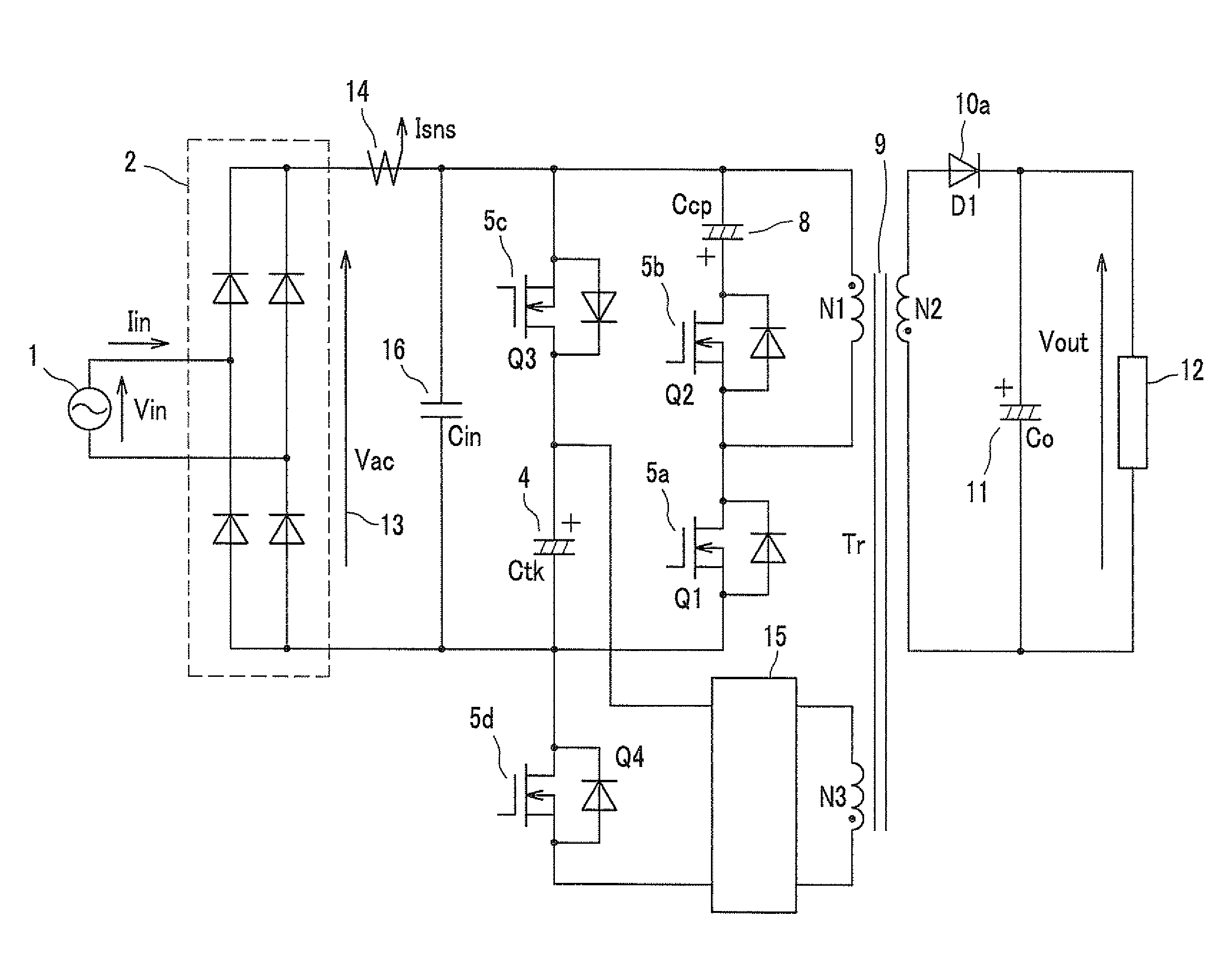
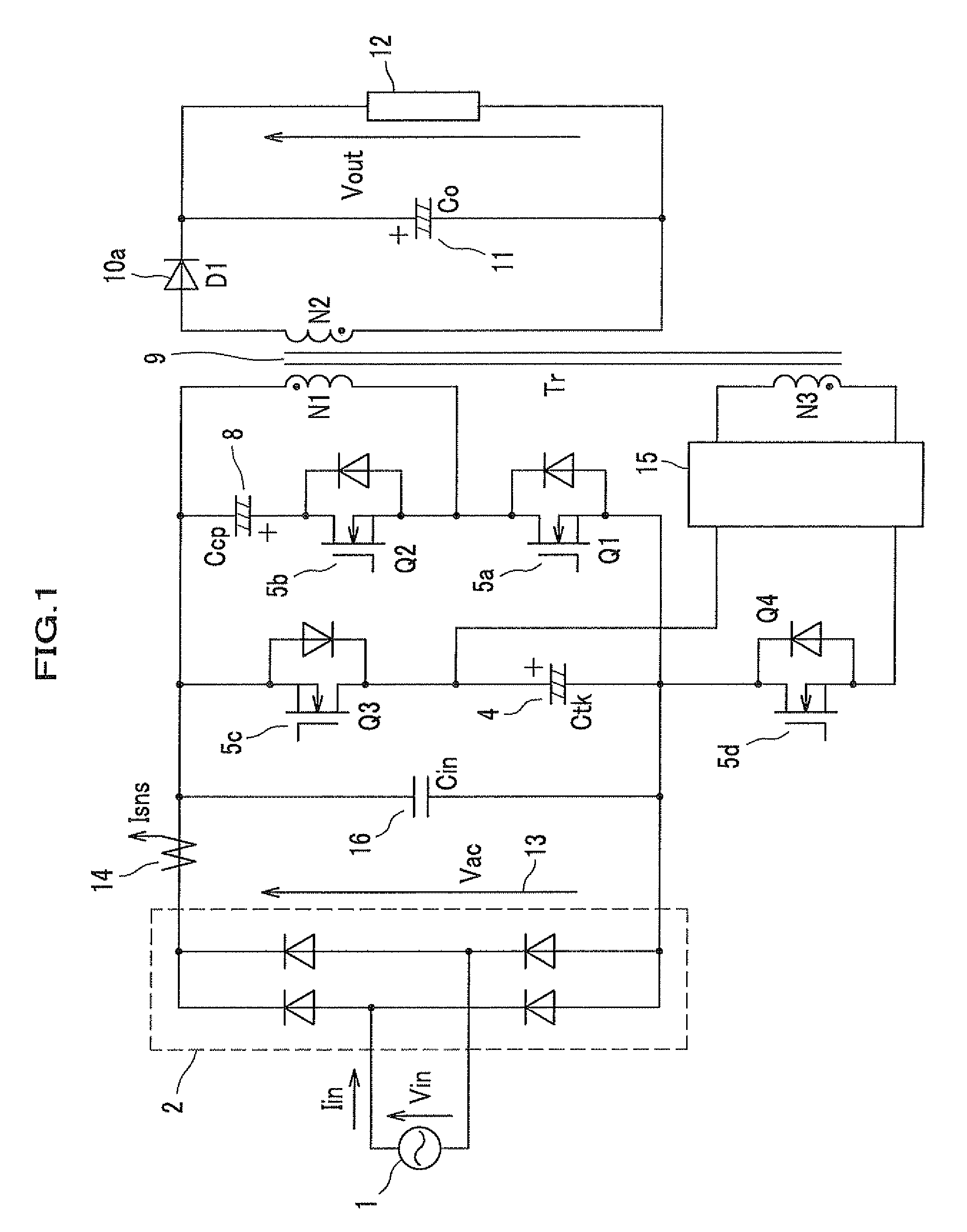
[0039]FIG. 1 is a circuit diagram showing a configuration of a switching power supply according to the first embodiment of the present invention.

[0040]As shown in FIG. 1, an AC power 1 by an AC power supply 1 is subjected to full-wave rectification (see FIG. 4, a full-wave rectification waveform 13) through a diode bridge 2. An input capacitor 16 (Cin) is connected between the DC-side positive and negative terminals of the diode bridge 2. The input capacitor 16 is for filtering, and has a capacitance of several μF.

[0041]The diode bridge 2 (a rectification function) and the input capacitor 16 (a filtering function, a smoothing function) configure first rectification-smoothing means.

[0042]A current between the diode bridge 2 and the input capacitor 16 is detected as an input current Isns having unde...

second embodiment

[0141]Next, an explanation will be given of a second embodiment with reference to FIG. 11.

[0142]FIG. 11 shows a specific circuit configuration of the charging circuit 15 shown in FIG. 1 in more detail as an embodiment.

[0143]The anode of a diode 10b (D2) is connected to the end (an opposite side of the black dot) of the third winding N3 of the insulation transformer 9, and a capacitor 48 is connected between the cathode of the diode 10b and the beginning (the black dot) of the secondary winding N2. The diode 10b has the cathode connected to the positive terminal of the instant power-suspension compensating capacitor 4 through a coil 49, and the negative terminal is connected to the negative terminal of the instant power-suspension compensating capacitor 4 through the power MOSFET 5d (the switching device Q4).

[0144]The power MOSFET 5d is an N-type (N-channel) device, has the drain connected to the negative terminal of the instant power-suspension compensating capacitor 4, and the sour...

third embodiment

A

[0153]FIG. 12A shows a simplest configuration as a function of the output voltage detector. That is, at the secondary side of the insulation transformer 9 (see FIG. 1), an output voltage (a voltage across both terminals of the output smoothing capacitor 11) is divided by a resistor 501 and a resistor 502, input into an ADC (Analog to Digital Converter, an A / D converter IC) 53 and is converted into a digital signal with pulse strings, and such a digital signal is transmitted to the primary side of the insulation transformer 9 (see FIG. 1) by a photocoupler 52, thereby causing the controller 51 to receive the signal.

[0154]In this case, in general, in order to transmit at least a clock signal and a control signal CS for a control to the ADC, and to receive a result as a serial signal, fast-speed photocouplers by what corresponds to at least three channels are necessary.

[0155]The reason why the photocoupler 52 is used is to insulate between the primary side and the secondary side in or...


PUM


Abstract

A switching power supply has a function of improving a power factor, and outputs insulated DC. The switching power supply performs two kinds of controls for switching devices exclusive to each other: controlling of a switching device provided in a direction in which the discharging of a primary-side smoothing capacitor is prohibited at the time of suspension of commercially available AC power and near the zero cross of an input voltage; and causing a switching device provided between the output side of a third winding and the primary-side smoothing capacitor to control a charging current, thereby charging a capacitor in a boosted manner.

Description

CROSS REFERENCE TO RELATED APPLICATION[0001]This application claims priority under 35 U.S.C. §119 to Japanese Patent Application No. 2010-275527 filed on Dec. 10, 2010, the disclosure of which is incorporated herein by reference.BACKGROUND OF THE INVENTION[0002]1. Field of the Invention[0003]The present invention relates to a switching power supply, and more specifically, a switching power supply which obtains a DC output power from an AC input power and which has a function of improving the power factor of an AC input current.[0004]2. Description of the Related Art[0005]In order to obtain a DC power from a commercially available power source (an AC power) through rectification and smoothing, a configuration of using a diode bridge and a smoothing capacitor is the simplest configuration. According to this configuration, however, the circuit configuration becomes a so-called capacitor-input type rectification circuit which has an input current allowed to flow only near the peak of a ...

Claims


Application Information

Patent Timeline
Patent Type & Authority Patents(United States)
IPC IPC(8): H02M1/36
CPCH02M1/36Y02B70/126H02M1/4258H02M2001/0096H02M2001/0058H02M3/33569Y02B70/10H02M1/0058H02M1/0096H02M3/01H02M3/33571
Inventor OUCHI, TAKAYUKIMOTEKI, MINORUKANOUDA, AKIHIKO
Owner TKR
Why Eureka
Try Eureka