Packaging material for cell

a battery and packaging material technology, applied in the field of film-shaped battery packaging materials, can solve the problems of increasing the production cost of battery packaging materials, difficult to keep up with the diversification in shape, and limit the weight reduction, so as to improve the moldability, reduce the size and thinning of batteries, and improve the effect of packaging materials

Active Publication Date: 2021-06-01
DAI NIPPON PRINTING CO LTD
View PDF29 Cites 0 Cited by
  • Summary
  • Abstract
  • Description
  • Claims
  • Application Information

AI Technical Summary

Benefits of technology

[0031]A battery packaging material according to the present invention includes a laminate including at least a coating layer, a barrier layer and a sealant layer in this order, and is not provided with an adhesive layer and a base material layer on the barrier layer which are provided in a conventional film-shaped battery packaging material. Therefore, the battery packaging material can be made thin, and can contribute to downsizing and thinning of batteries.
[0032]In the battery packaging material according to the present invention, the laminate that forms the battery packaging material has a piercing strength of 5 N or more as measured in accordance with JIS 1707:1997, and the coating layer has a dielectric breakdown voltage of 1.0 kV or more as measured in accordance with JIS C2110-1. Thus, excellent moldability and insulation quality can be imparted to the battery packaging material, and generation of cracks, pinholes and the like can be suppressed even when the molding depth during deep drawing molding is increased.
[0033]Since the dielectric breakdown voltage of the coating layer that forms the battery packaging material is 1.0 kV or more, an insulation quality as a battery packaging material is effectively improved.
[0034]Further, in the battery packaging material according to the present invention, the coating layer provided on the barrier layer is formed of a cured product of a resin composition containing a thermosetting resin and a curing accelerator, and therefore in a step of curing the coating layer, the layer can be cured in a short time without necessity of aging under a high-temperature condition. Thus, the lead time can be reduced, and further, occurrence of product defects due to exposure to a high-temperature condition for a long period of time can be prevented.

Problems solved by technology

However, metallic battery packaging materials that have often been heretofore used have the disadvantage that it is difficult to keep up with diversification in shape, and there is a limit on weight reduction.
However, thinning of the resin film has limitations in terms of production, and also has the problem that the processing cost required for thinning of the resin film causes an increase in production cost of a battery packaging material.
However, when in place of an adhesive layer and a base material layer, a coating layer is formed using a thermosetting resin in a film-shaped battery packaging material, it is required to perform aging under a high-temperature condition for several days to several weeks as a curing step, and therefore the lead time is increased, so that product defects occur due to exposure to a high-temperature condition and a temperature change for a long period of time.

Method used


Image

  • Packaging material for cell
  • Packaging material for cell

Examples


example

[0132]The present invention will be described in detail below by showing examples and comparative examples. It is to be noted, however, that the present invention is not limited to the examples.

[Production of Battery Packaging Material]

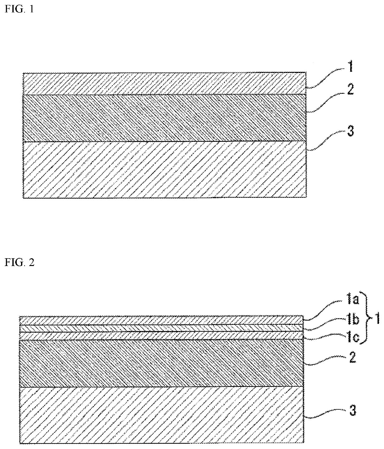
[0133]A coating layer was formed, in a thickness as shown in Tables 1 and 2, on a barrier layer formed of aluminum foil (thickness: 40 μm) subjected to a chemical conversion treatment on both surfaces. Specifically, a thermosetting resin composition as shown in Tables 1 and 2 was applied to the barrier layer, and cured to laminate a coating layer on the barrier layer. In production of the battery packaging material, the coating layer was cured in an extremely short time of 30 seconds at 160° C., so that the lead time was considerably reduced. Details of the resin composition that forms the coating layer are as follows. The chemical conversion treatment of the aluminum foil used as the barrier layer was performed by applying to both the surfaces of the...


PUM

PropertyMeasurementUnit
dielectric breakdown voltageaaaaaaaaaa
thicknessaaaaaaaaaa
thicknessaaaaaaaaaa

Abstract

A film-shaped packaging material for a cell in which a coating layer is provided as the outermost layer instead of a substrate layer and an adhesive layer in a conventional film-shaped packaging material for a cell, thereby making it possible to produce a thinner film; wherein the packaging material is provided with exceptional moldability and insulation performance and enables lead time to be reduced. The packaging material is a laminate having at least a coating layer, a barrier layer, and a sealant layer in the stated order, the coating layer including a single- or multiple-layer configuration formed by a cured product of a resin composition containing a heat-curable resin and curing accelerator, the laminate having a piercing strength of at least 5 N, as measured in compliance with JIS 1707:1997, and the coating layer having a breakdown voltage of at least 1.0 kV, as measured in compliance with JIS C2110-1.

Description

TECHNICAL FIELD[0001]The present invention relates to a film-shaped battery packaging material which is made thin by providing a coating layer as an outermost layer on a barrier layer, the battery packaging material having excellent moldability and an insulation quality and being capable of reducing the lead time.BACKGROUND ART[0002]Various types of batteries have been developed heretofore, and in every battery, a packaging material is an essential member for sealing battery elements such as an electrode and an electrolyte therein. Metallic packaging materials have been often used heretofore as battery packaging materials.[0003]On the other hand, batteries are required to be diversified in shape and to be thinned and lightened with improvement of performance of electric cars, hybrid electric cars, personal computers, cameras, mobile phones and so on. However, metallic battery packaging materials that have often been heretofore used have the disadvantage that it is difficult to keep ...

Claims


Application Information

Patent Timeline
Patent Type & Authority Patents(United States)
IPC IPC(8): B32B27/32H01M2/02B65D65/40B32B7/02B32B27/20B32B15/088B32B27/28B32B27/36B32B7/12B32B23/04B32B15/092B32B15/18B32B7/04B32B15/085B32B15/095B32B25/20B32B15/082B32B27/30B32B27/08B32B27/34B32B25/18B32B15/20B32B27/42B32B25/16B32B27/40B32B27/38B32B15/09B32B15/06B32B15/098B32B25/14H01M50/119H01M50/121H01M50/129H01M50/133
CPCH01M2/0287B32B7/02B32B7/04B32B7/12B32B15/06B32B15/082B32B15/085B32B15/088B32B15/09B32B15/092B32B15/095B32B15/098B32B15/18B32B15/20B32B23/042B32B25/14B32B25/16B32B25/18B32B25/20B32B27/08B32B27/20B32B27/281B32B27/285B32B27/306B32B27/308B32B27/32B32B27/322B32B27/34B32B27/36B32B27/365B32B27/38B32B27/40B32B27/42B65D65/40H01M2/0277H01M2/0285B32B2250/02B32B2250/03B32B2270/00B32B2307/206B32B2307/302B32B2307/31B32B2307/50B32B2307/71B32B2307/714B32B2307/7244B32B2307/7246B32B2307/732B32B2307/746B32B2307/752B32B2457/10B32B2457/16B32B2553/00Y02E60/10H01M50/124H01M50/133H01M50/121H01M50/129H01M50/119
Inventor HASHIMOTO, YOUHEIYAMASHITA, RIKIYAUEDA, SHUNSUKE
Owner DAI NIPPON PRINTING CO LTD
Why Eureka
Try Eureka