Method for the manufacture of a composite article

a composite article and manufacturing method technology, applied in the field of composite article manufacturing, can solve the problems of increasing the weight of the additional material, reducing the strength of the structural element, and requiring expensive machines to perform these operational steps, so as to achieve the effect of reducing the tension of the material, no galvanic corrosion, and low thermal expansion coefficien

Inactive Publication Date: 2014-01-21
SAAB AB
View PDF10 Cites 1 Cited by
  • Summary
  • Abstract
  • Description
  • Claims
  • Application Information

AI Technical Summary

Benefits of technology

[0008]The former is in accordance with one embodiment of the invention water soluble and comprises a fiber material and an adhesive and water. The fiber material is for example a fabric such as a woven textile, glass, carbon, aramide etc. For example, a dishcloth could serve as the fiber material. The adhesive is for example a starch such as starch from corn, potatoes or wheat or an adhesive of another type such as polyvinyl alcohol (PVA). For example, paperhangers paste can be used in manufacturing the former, said paperhangers paste comprising both starch and water. In using the water soluble former it is possible to manufacture composite articles with very complex geometries in only one cure operation. The former is then dissolved in water after the curing step.
[0011]The at least one fitting is preferably made of a material having the same coefficient of thermal expansion as the composite layer and composite plate. Then, as the coefficient of thermal expansion is not higher than the coefficient of thermal expansion of the composite plate and composite layer, tension in the material is minimized. Further, as the coefficient of thermal expansion is not smaller than the coefficient of thermal expansion of the composite plate and composite layer, the fitting is detachably or fixedly integrated in the composite article material in the curing step. It is also advantageous if the fitting material has such characteristics that it provides substantially no galvanic corrosion against the composite material. Titanium is an example of a material both having a low coefficient of thermal expansion and providing substantially no galvanic corrosion against the composite material. Therefore a fitting made of titanium or a titanium based alloy is preferably used in combination with a carbon fiber composite material in the composite plate and composite layer, said carbon fiber composite having a substantially equal coefficient of thermal expansion. On the other hand, if the composite plate and composite layer is made of a glass fiber composite, then the fitting(s) can for example be made of stainless steel or aluminum.
[0015]In using the method according to the invention, composite articles can be manufactured having complex geometries, which today are regarded as impossible to obtain, and having perfect fitting surfaces or having fittings integrated in the composite articles. As the fittings can be integrated in the composite article at the same time as the composite article is manufactured, many economical advantages are obtained. For example, labor costs can be decreased as the time consuming step of mounting the fittings is practically eliminated and the areas of premises can be decreased as no areas for performing the mounting of fittings are necessary. Further, it is much easier to obtain the tolerance chain compared to when using conventional techniques. For the manufacture of composite articles in accordance with the invention, important tolerance determined dimensions for the final article can be determined, and the manufacture can then be performed such that these tolerances are kept.

Problems solved by technology

It is very time consuming and / or requires expensive machines to perform these operational steps with the tolerances required.
Further, these operational steps tend to decrease the strength of the structural element and therefore calculations must be made regarding the strength of the structural element in the areas around the fittings and the structural element must be made thicker in accordance with the calculations.
The requirement of a thicker structural element in the areas of the fittings implies that the structure of the element becomes more complex and has a higher weight due to the additional material.

Method used


Image

  • Method for the manufacture of a composite article
  • Method for the manufacture of a composite article
  • Method for the manufacture of a composite article

Examples


Embodiment Construction

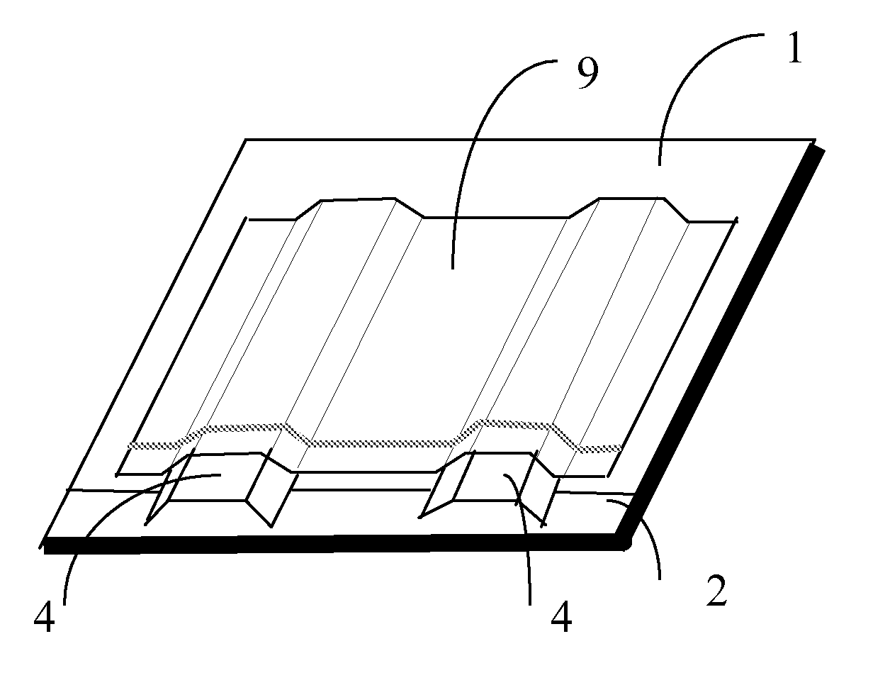
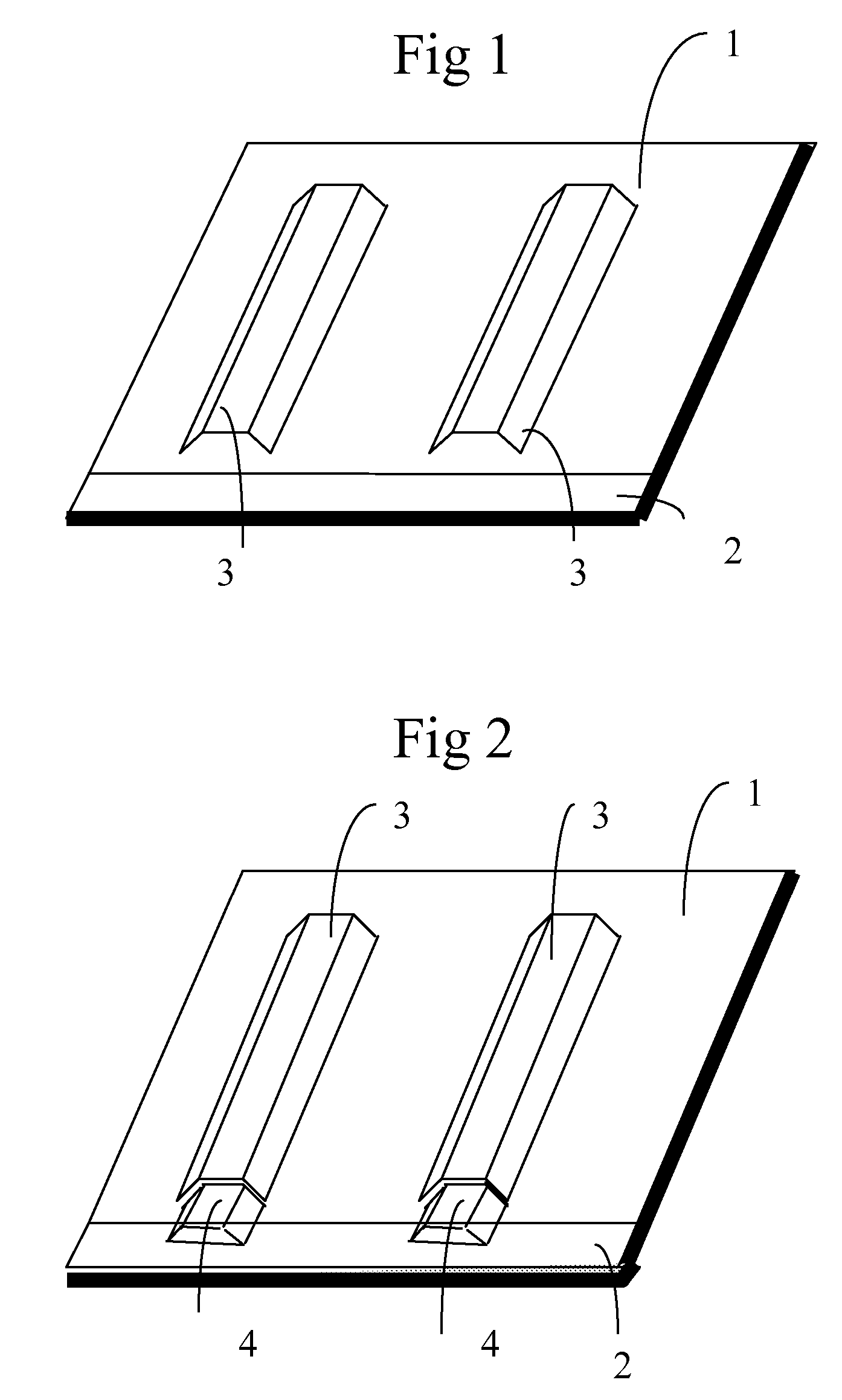
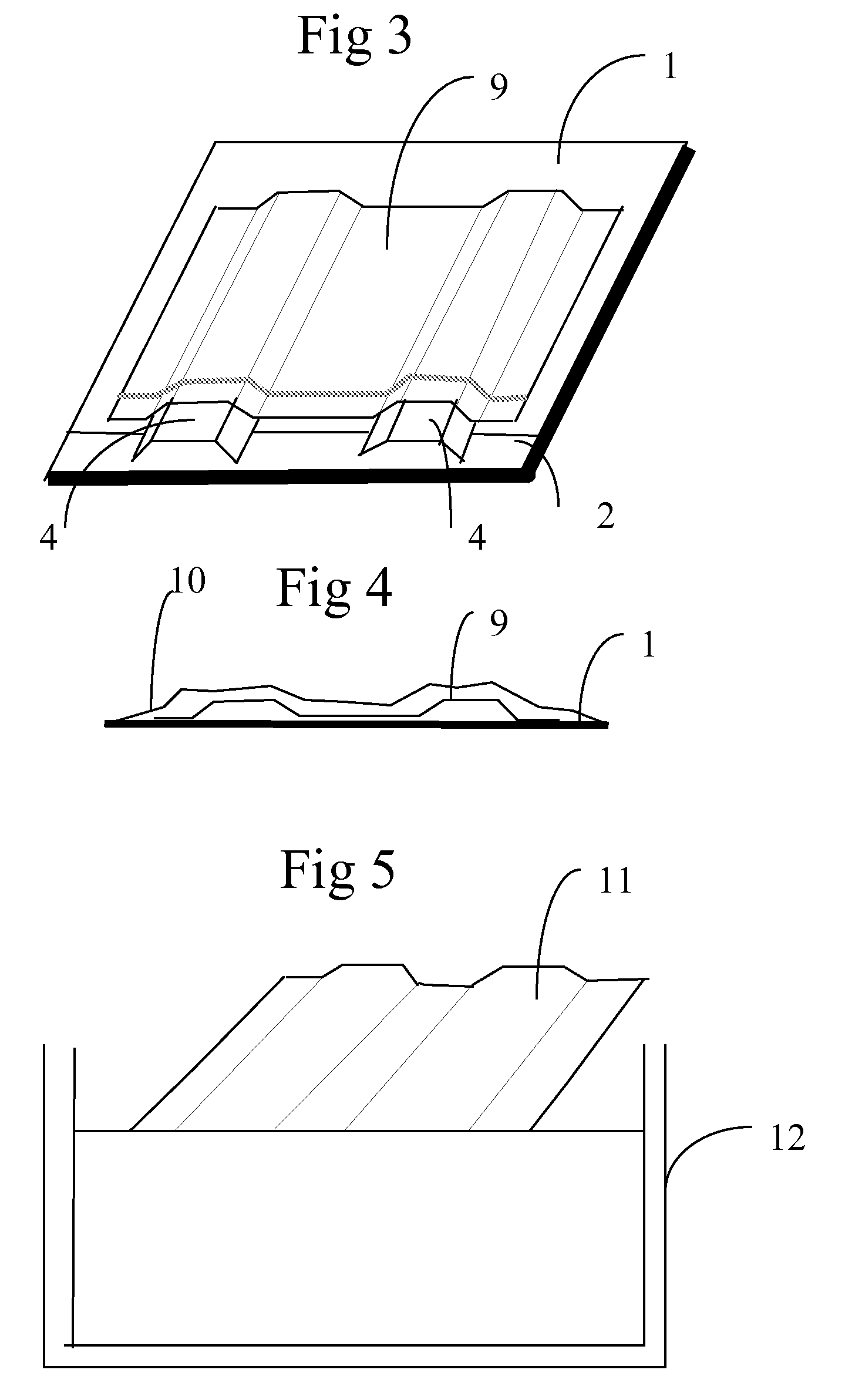
[0028]In FIG. 1, a composite plate 1 is arranged on a base plate 2. The base plate 2 is a thick sheet, for example made of metal. In the shown figure, the base plate has larger dimensions than the composite plate 1. Two formers 3 are arranged on top of the composite plate 1. The formers 3 are for example made of a water-soluble stabilizing fiber composite.

[0029]In FIG. 2, a fitting 4 is arranged in the extension of each former 3. The fittings are intended to be integrated in the final article such that it is either detachable or fixed after curing. In the alternative embodiment of FIG. 8, the base plate 2 is provided with pins 5 mounted in locations and formed so as to fix the fittings 4 (not shown in FIG. 2) in a predetermined position. In another alternative embodiment, as disclosed in FIG. 9, a laser arrangement 6 is mounted for example in the ceiling. The laser arrangement is arranged to emit a laser curtain in a predetermined number of directions. The directions are set such th...


PUM

PropertyMeasurementUnit
pressureaaaaaaaaaa
temperatureaaaaaaaaaa
pressureaaaaaaaaaa

Abstract

The present invention relates to a method for the manufacture of a composite article comprising a composite plate (1) and at least one fitting (4). The method is characterized by the steps of arranging at least one former on said composite plate (1), arranging at least one fitting (4) on said composite plate (1), producing a lay-up by applying a composite material layer (9) least partly covering an external surface of the former and of the fitting, and curing the layup in a curing process. After curing, said composite material layer (9) forms the walls of a stiffener and at least partly encloses the fitting so as to support it in a predetermined position.

Description

TECHNICAL FIELD[0001]The present invention relates to a method for the manufacture of a composite article comprising at least one.[0002]The present invention further relates to a composite article comprising at least one fitting and obtainable by the method above.PRIOR ART[0003]The fabrication of many items and structural elements, such as vehicles, vessels and aircraft, out of curable composite materials containing layers of fibers or metals joined by means of an adhesive layer of for example thermoplastic, is known. Such composite materials are distinguished by high strength and relatively low weight. These distinguishing properties have resulted in it becoming increasingly common in the aviation industry to use items containing composite materials.[0004]Conventionally, structural elements of composite materials are manufactured by arranging a former made of metal on a base plate and laying up laminate layers on the former, so that the laminate lies against the surface of the form...

Claims


Application Information

Patent Timeline
Patent Type & Authority Patents(United States)
IPC IPC(8): B32B9/04B29C65/00B29C70/44B27N3/10
CPCB29C70/86B29C70/342B29C33/52Y10T428/31504
Inventor PETERSSON, MIKAELWEIDMANN, BJORNKROGAGER, MAXTURESSON, INGEMAR
Owner SAAB AB
Why Eureka
Try Eureka