
Serial-line-scan-encoded multi-color fluorescence microscopy and imaging flow cytometry

a fluorescence microscopy and multi-color technology, applied in the field of biological cell count and characterization, to achieve the effect of improving signal-to-noise characteristics

Inactive Publication Date: 2014-01-28
BIO RAD LAB INC
View PDF27 Cites 8 Cited by
  • Summary
  • Abstract
  • Description
  • Claims
  • Application Information

AI Technical Summary

Benefits of technology

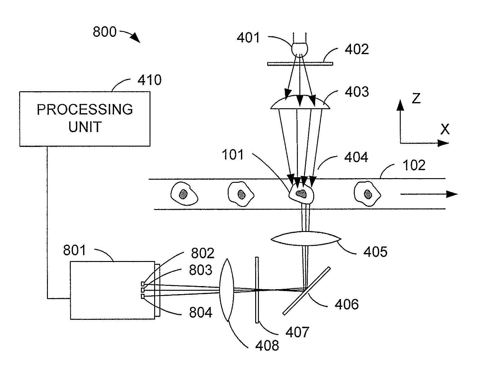
[0012]In another embodiment, a method of performing cytometry comprises illuminating a scanning region using a light source, and focusing, using an optical system, an image of a portion of the scanning region onto at least two parallel linear light sensors. The method of this embodiment further comprises repeatedly taking readings of light falling on the two parallel light sensors while a cell is transported through the scanning region and illuminated by the light source. In some embodiments, the method further comprises combining images gathered by the individual linear light sensors to form an image with improved signal-to-noise characteristics as compared with an image gathered by a single linear light sensor. Combining images may further include digitally combining pixel values from the respective images corresponding to substantially the same respective locations on the cell. Combining images may further include combining images using time delay integration. In some embodiments, the light source produces illumination including light in at least first and second wavelength bands, and the method further comprises directing, using the optical system, light emitted from the cell in a third wavelength band primarily to one of the two parallel light sensors, and directing, using the optical system, light emitted from the cell in a fourth wavelength band primarily to the other of the two parallel linear light sensors. In some embodiments, the method further comprises focusing, using the optical system, an image of a portion of the scanning region onto at least two sets of parallel linear light sensors, each set comprising at least two linear light sensors.

Problems solved by technology

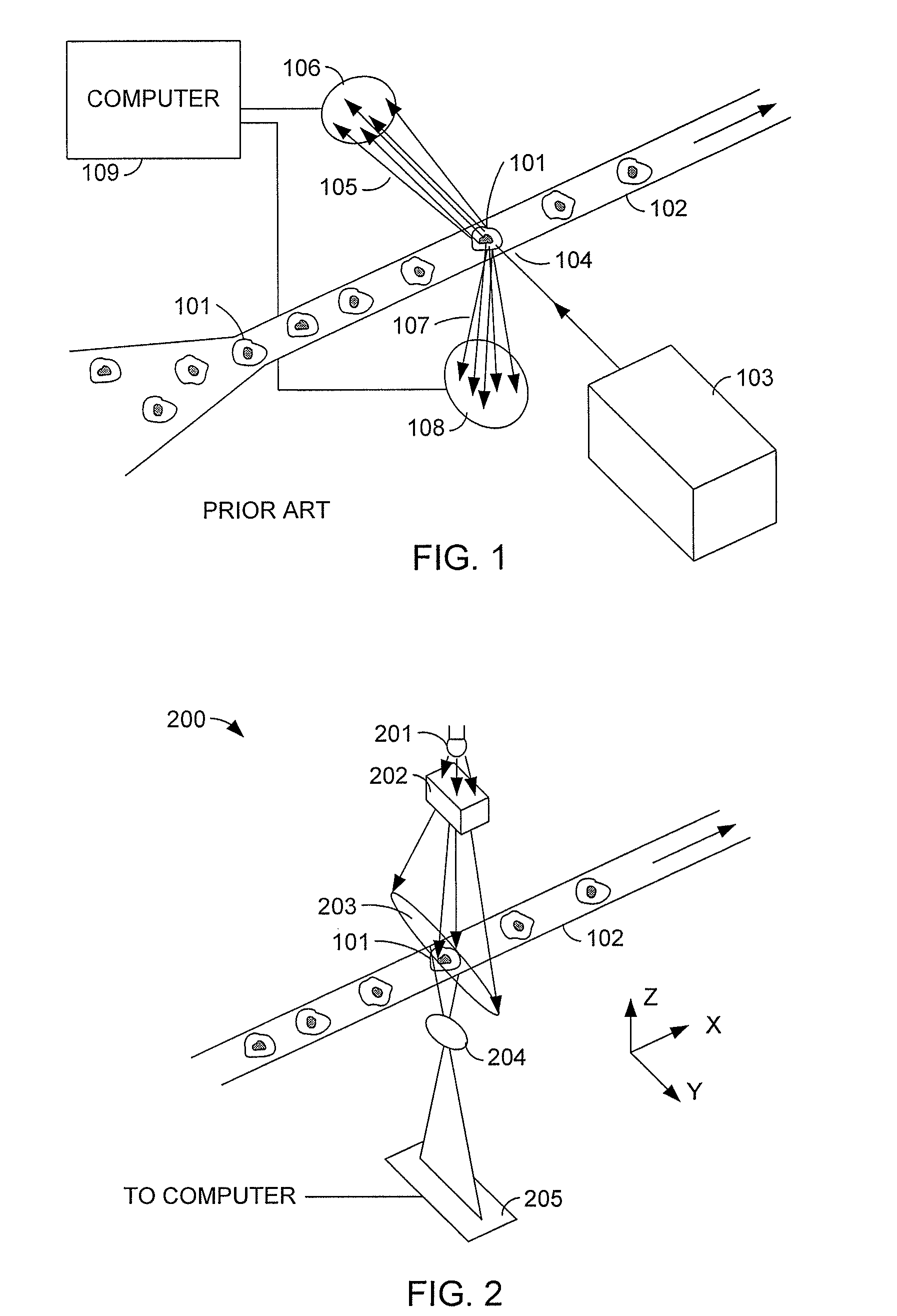
The technique shown in FIG. 1 relies entirely on measurements of scattered light to infer information about the cell structure, but does not produce an image of any particular cell.

Method used


Image

  • Serial-line-scan-encoded multi-color fluorescence microscopy and imaging flow cytometry
  • Serial-line-scan-encoded multi-color fluorescence microscopy and imaging flow cytometry
  • Serial-line-scan-encoded multi-color fluorescence microscopy and imaging flow cytometry

Examples


Embodiment Construction

[0023]FIG. 2 shows a simplified conceptual diagram of a high-speed, high-resolution line scan image cytometry system 200 in accordance with an embodiment. The system of FIG. 2 is a flow cytometry system, although one of skill in the art will recognize that embodiments of the invention may be utilized in other kinds of cytometry as well.

[0024]Cells 101 are entrained in fluid to progress through tube 102 in single file. The system may be used to characterize cells of many different kinds, but in a typical application, cells 101 may be, for example, about 10 to 20 micrometers across, and may progress through tube 102 at a speed of, for example, 10 millimeters per second. A light source 201 provides field of light 203 onto tube 102. Light source 201 may be a laser, a light-emitting diode, an incandescent light source, a fluorescent light source or another kind of light source. Light source 201 may produce substantially monochromatic light, broad spectrum light, or light containing two o...


PUM


Abstract

A system for performing high-speed, high-resolution imaging cytometry utilizes a line-scan sensor. A cell to be characterized is transported past a scan region. An optical system focuses an image of a portion of the scan region onto at least one linear light sensor, and repeated readings of light falling on the sensor are taken while a cell is transported though the scan region. The system may image cells directly, or may excite fluorescence in the cells and image the resulting light emitted from the cell by fluorescence. The system may provide a narrow band of illumination at the scan region. The system may include various filters and imaging optics that enable simultaneous multicolor fluorescence imaging cytometry. Multiple linear sensors may be provided, and images gathered by the individual sensors may be combined to construct an image having improved signal-to-noise characteristics.

Description

[0001]This application claims priority to U.S. Provisional Patent Application No. 61 / 162,072, filed Mar. 20, 2009, and U.S. Provisional Patent Application No. 61 / 232,113, filed Aug. 7, 2009, the disclosures of which are incorporated herein by reference for all purposes.BACKGROUND OF THE INVENTION[0002]Cytometry is a technical specialty concerned with the counting and characterization of biological cells. FIG. 1 shows a simplified diagram of one technique known as flow cytometry. In a basic form of flow cytometry, cells 101 are suspended in a fluid and entrained single-file in a narrow transparent tube 102. The entrainment can be accomplished by any of several methods, including hydrodynamic focusing. A light source 103 illuminates each cell 101 as it passes a measurement location 104. Light source 103 may be, for example, a laser. Light from light source 103 is scattered by the cell 101 being measured. Some light 105 is scattered generally in the same direction as it traveled to rea...

Claims


Application Information

Patent Timeline
Patent Type & Authority Patents(United States)
IPC IPC(8): G06K9/00
CPCG01J3/4406G01N2021/6419G01J3/02G01N21/6458G01N15/1475G01N15/1429G01N2021/6421G01N15/147G01J3/04G01J3/10G01J3/36G01J3/0208G01N15/1425G01N21/6486
Inventor HENG, XINPATT, PAUL
Owner BIO RAD LAB INC
Learn More