Externally arranged ultrahigh frequency partial discharge detection sensor
A technology of partial discharge detection and ultra-high frequency, which is applied in the direction of testing dielectric strength, etc., can solve the problem that the detection effect of ultra-high frequency detection sensor is not very good, so as to avoid external interference, good signal-to-noise ratio characteristics, and small signal distortion Effect
- Summary
- Abstract
- Description
- Claims
- Application Information
AI Technical Summary
Problems solved by technology
Method used
Image
Examples
Embodiment 1
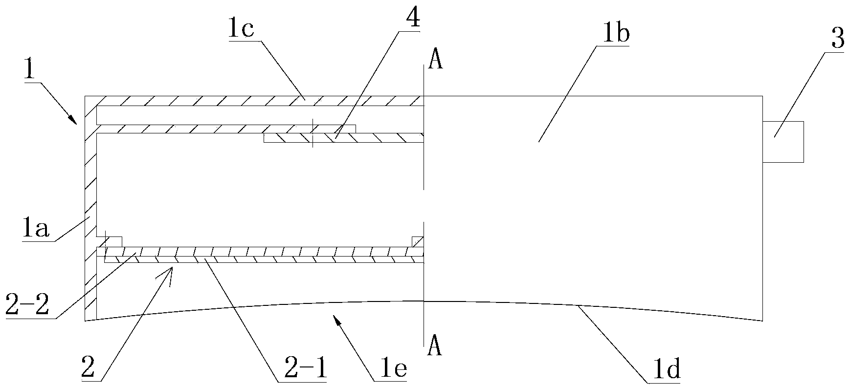
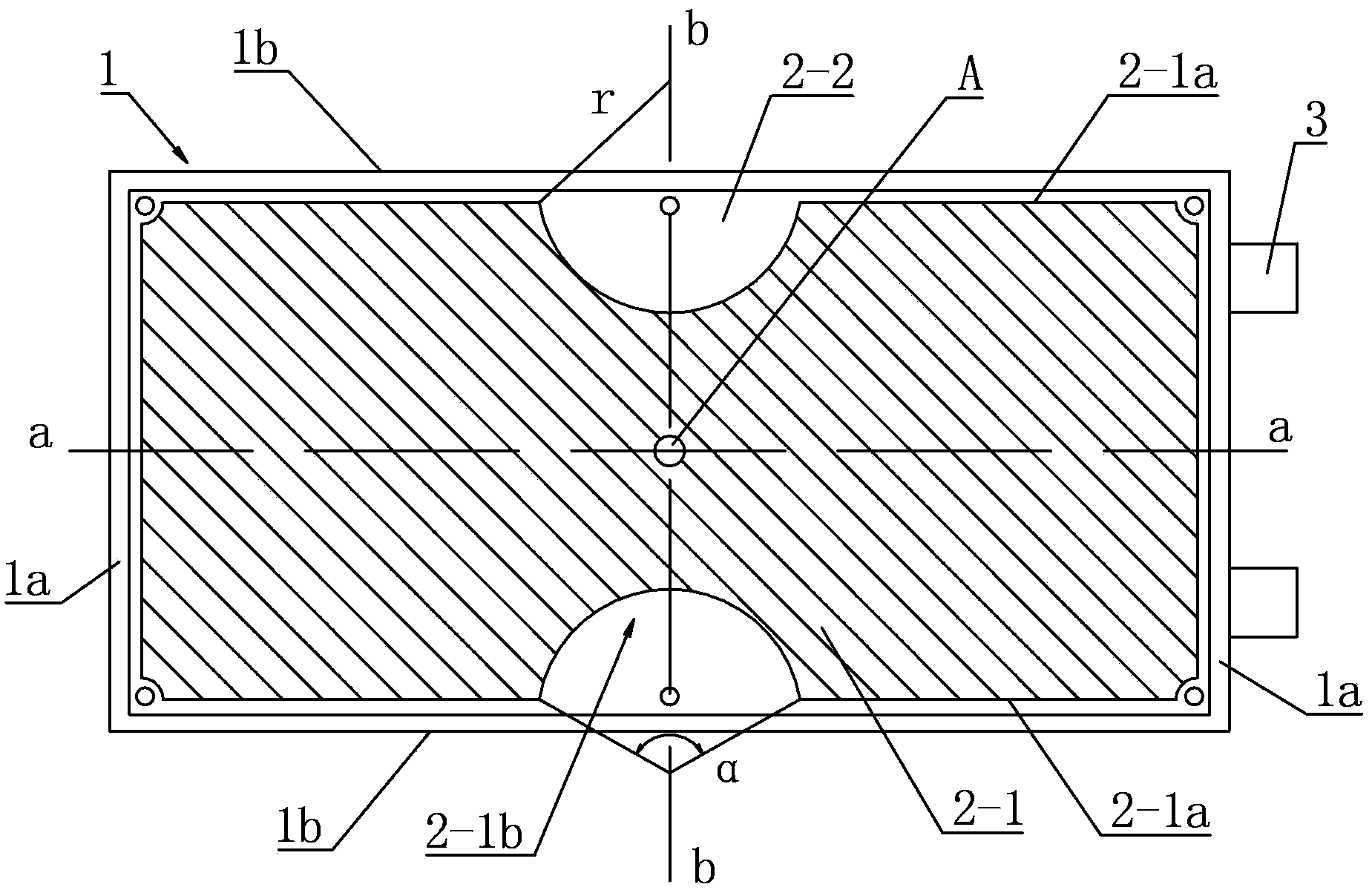
[0031] Such as figure 1 with figure 2 As shown, the external UHF partial discharge detection sensor of the present invention includes a metal shielding shell 1 , a microstrip antenna 2 , a coaxial cable connector 3 and an integrated circuit board 4 . For ease of description, the figure 1 The center line A-A in defines the direction of up and down.
[0032] The shielding case 1 of this embodiment is a box shape with an open bottom consisting of a pair of short side walls 1a, a pair of long side walls 1b, and a top wall 1c connected to the short side walls 1a and the long side walls 1b. 1a is arranged adjacent to the long side wall 1b, wherein the lower bottom edge 1d of the long side wall 1b is an arc-shaped bottom edge, and the arc-shaped lower bottom edge 1d is concave upward from the lower edge of the long side wall 1b. The shape of the pot insulator is corresponding, so that it can be placed on the pot insulator during inspection. The short side wall 1a is a square str...
Embodiment 2
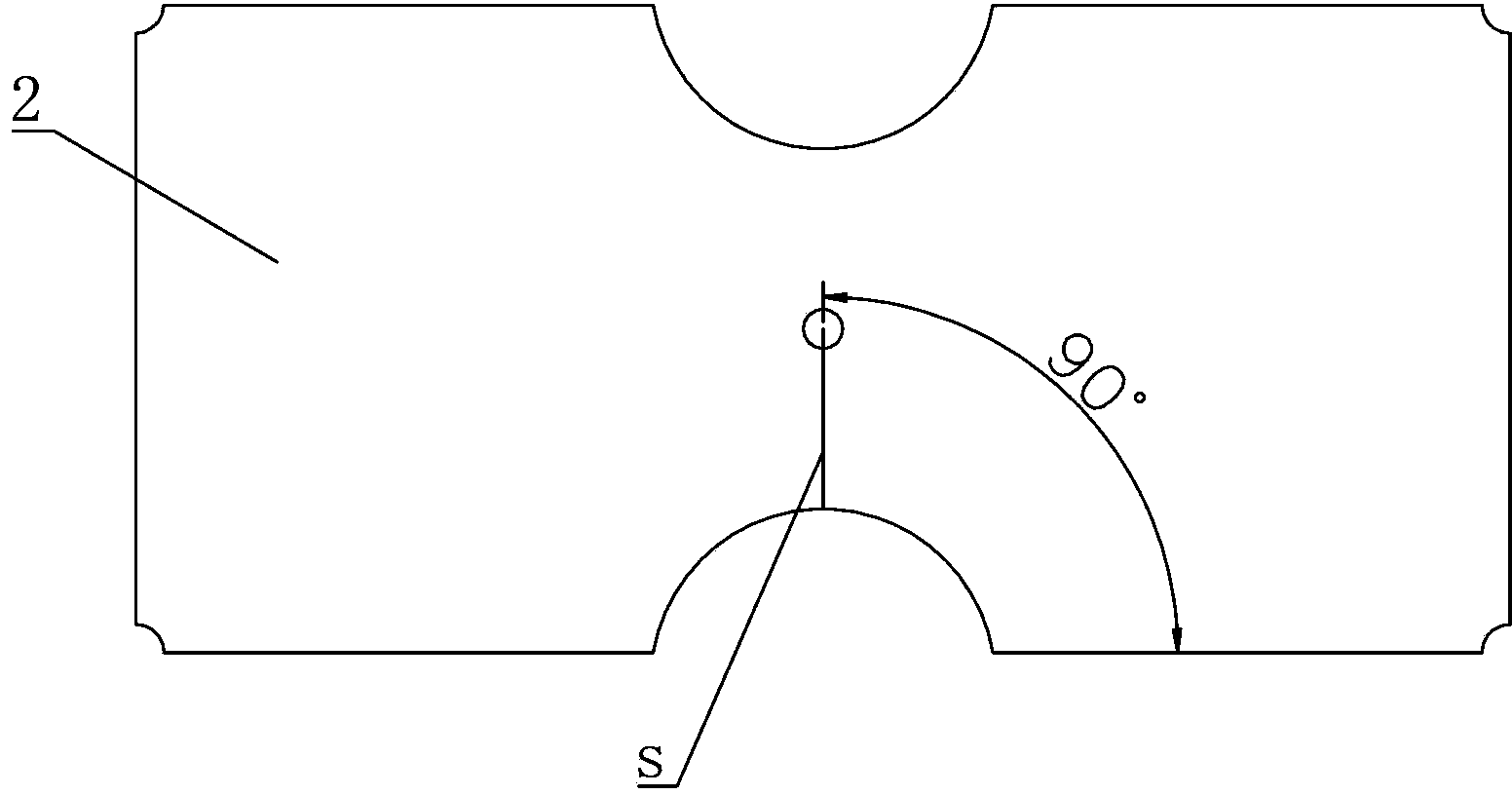
[0039] The difference between this embodiment and Embodiment 1 is that: in this embodiment, the angle β between the coaxial probe feeder s and the microstrip antenna 2 is 5°. Figure 7 Be the standing wave ratio figure of the microstrip antenna of embodiment 2, by Figure 7 It can be seen that the microstrip antenna in this embodiment has a standing wave ratio below 2 in the frequency range of 1-4 GHz and a wide impedance bandwidth, which can well cover the useful detection frequency band of partial discharge.
Embodiment 3
[0041] The difference between this embodiment and Embodiment 1 is that: in this embodiment, the angle β between the coaxial probe feeder s and the microstrip antenna 2 is 10°. Figure 8 It is the standing wave ratio diagram of the microstrip antenna of embodiment 3. Depend on Figure 8 It can be seen that the microstrip antenna in this embodiment has a standing wave ratio below 2 in the frequency range of 1.75-4.2 GHz, and can better cover the useful detection frequency band of partial discharge.
PUM
 Abstract
Description
Claims
Application Information
 - R&D
- Intellectual Property
- Life Sciences
- Materials
- Tech Scout
- Unparalleled Data Quality
- Higher Quality Content
- 60% Fewer Hallucinations
Browse by: Latest US Patents, China's latest patents, Technical Efficacy Thesaurus, Application Domain, Technology Topic, Popular Technical Reports.
© 2025 PatSnap. All rights reserved.Legal|Privacy policy|Modern Slavery Act Transparency Statement|Sitemap|About US| Contact US: help@patsnap.com


