Chassis for a motor vehicle having an electrical axle

a technology for motor vehicles and axles, applied in the direction of electric propulsion mounting, electric devices, gearing, etc., can solve the problems of inability to permit any relevant change in length, the design of chassis or axles disadvantageously relates to rigid portal axles, etc., to increase the maximum torque, reduce consumption, and increase the power of the vehicle

Active Publication Date: 2014-02-04
DR ING H C F PORSCHE AG
View PDF100 Cites 22 Cited by
  • Summary
  • Abstract
  • Description
  • Claims
  • Application Information

AI Technical Summary

Benefits of technology

[0012]A force-fitting connection between the step-down gear mechanism and the associated wheel by the cardan shaft allows torques to be transmitted without the need for the axle to be rigid. Consequently, in contrast to the motor vehicles described above, the chassis can be provided with an independent wheel suspension system. This considerably expands the field of use for the chassis, in particular to cars in which it is advantageous, for driving comfort and safety to have each wheel can undergo spring compression and spring extension individually and independently of the other wheels of the vehicle.
[0022]A torque sensor preferably is provided for detecting the torque in the drive train of the respective wheel. As a result, the electric drives can be controlled individually in accordance with the desired torque that is to be introduced by the respective wheel.
[0025]The chassis of the invention therefore is used in a vehicle that can be driven by a hybrid drive. The hybrid system functions to increase the vehicle power and reduce consumption, in particular in a sports car, by adding the additional electrical drive machines and the energy storage means. A positive or negative torque that is specific to the wheel can be impressed on the drive shafts at the front axle of the motor vehicle by the two electrical machines. The vehicle is accelerated (motor mode) or decelerated (generator mode) by operating the electrical machines. The energy storage means is discharged or charged in the process.
[0026]The electrical axle transmits torque from the electrical machines to the front wheels of the vehicle by a suitable step-down means. To this end, a two-stage gear mechanism comprising a planetary gear stage and a spur gear stage is flange-connected to the output shafts of each electrical machine. The output shafts of the gear mechanism are connected directly to the wheels by cardan shafts. A separable clutch is not provided. The gear mechanism transmission ratios allow a significant increase in the maximum torque that can be transmitted by the electrical axle. Therefore, the torque produced at the respective wheel readily can be multiplied, for example, by a factor of 6 to 8.

Problems solved by technology

The above-described chassis or axle designs disadvantageously relate to rigid portal axles.
Furthermore, electrical machines with coaxially arranged rotational axes do not permit any relevant change in length.

Method used


Image

  • Chassis for a motor vehicle having an electrical axle
  • Chassis for a motor vehicle having an electrical axle

Examples


Embodiment Construction

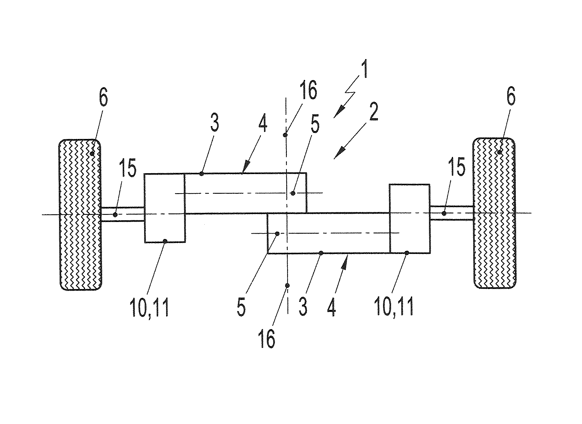
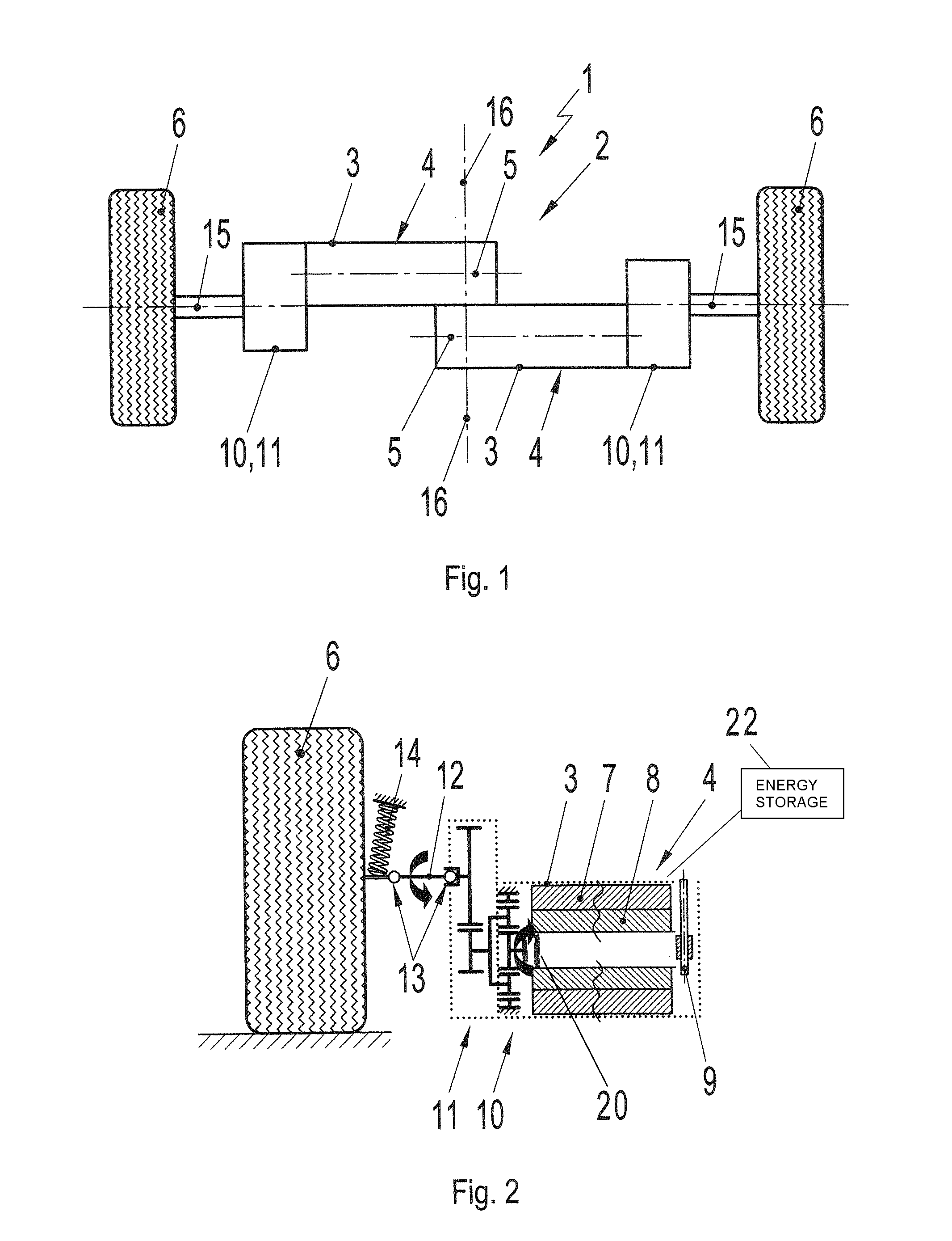
[0031]The motor vehicle equipped with the chassis of the invention preferably is a car intended to be used in racing. The individually suspended wheels of the car that are associated with the rear axle are driven by an internal combustion engine. The wheels associated with the front axle also are individually suspended and can be driven by electric motor to apply an additional drive torque by means of the front wheels. The following description relates to the design of the motor vehicle in the region of the front axle and the chassis of the invention in this respect. This chassis 1 has an electrical axle 2 that is designed as a portal axle with two portal axle sections in the form of tubes that represent the housings 3 for accommodating two electrical machines 4. The housings 3 and the electrical machines 4 are arranged parallel and next to one another in relation to their rotation axes 5, with the spacing between the rotation axes 5, taking into account the outside diameter of the ...


PUM


Abstract

A chassis (1) for a motor vehicle has an electrical axle (2) with two electrical machines (4) for respectively driving two wheels (6). The chassis (1) also has a step-down gear mechanism (10, 11) arranged between the respective electrical machine and the associated wheel. Each step-down gear mechanism is connected to the respective wheel by a cardan shaft. The respective rotation axes (5, 5) of the two electrical machines are arranged parallel and next to one another. The chassis enables each wheel to be mounted in a non-rigid manner and permits the overall length of the electrical machines to be varied on account of the arrangement of the rotation axes of the electrical machines.

Description

CROSS-REFERENCE TO RELATED APPLICATION[0001]This application claims priority under 35 USC 119 to German Patent Application No. 10 2010 010 438.8, filed on Feb. 26, 2010, the entire disclosure of which is incorporated herein by reference.BACKGROUND OF THE INVENTION[0002]1. Field of the Invention[0003]The invention relates to a chassis for a motor vehicle, having an electrical axle with two electrical machines and wheels rotatably mounted in the region of the two ends of the electrical axle. Each wheel to be driven by one of the electrical machines. A step-down gear mechanism is arranged between the respective electrical machine and the wheel associated with the electrical machine.[0004]2. Description of the Related Art[0005]DE 295 18 401 U1 discloses the above-described type of chassis used in a utility vehicle. This utility vehicle is a city bus for transporting people. A carriage floor is arranged at a low level of the city bus and runs through the entire bus, including the region ...

Claims


Application Information

Patent Timeline
Patent Type & Authority Patents(United States)
IPC IPC(8): B60K6/48
CPCB60K17/046B60K7/0007B60L2220/46B60K2007/0046B60K2007/0061
Inventor ARMBRUSTER, DANIELHENNINGS, STEPHAN
Owner DR ING H C F PORSCHE AG
Why Eureka
Try Eureka