Radiological image detection apparatus and method of manufacturing the same

a technology of radiological image and detection apparatus, which is applied in the direction of radiation intensity measurement, x/gamma/cosmic radiation measurement, instruments, etc., can solve the problem of reducing the quantity of x-ray entering the scintillator, deteriorating the performance of an element, and absorbing a large amount of x-ray, so as to maximize the image quality of the detected image and reduce the radiation absorption factor. , the effect of deterioration of the thin film

Active Publication Date: 2014-02-04
FUJIFILM CORP
View PDF8 Cites 4 Cited by
  • Summary
  • Abstract
  • Description
  • Claims
  • Application Information

AI Technical Summary

Benefits of technology

[0011]An illustrative aspect of the present invention is to provide: a radiological image detection apparatus capable of solving the drawbacks in the radiological image detection apparatus including a substrate-free photodetecting unit and reducing a degree of radiation absorbed by the photodetecting unit, thereby being able to increase an amount of radiation entering the scintillator; a manufacturing method of the radiological image detection apparatus; and an radiological imaging cassette having the radiological image detection apparatus.
[0016]With the processes or configurations discussed above, the photodetecting unit has the protective member. Even if the substrate of the photodetecting unit is peeled off, the thin film portion will be protected. The presence of such a protective member enables protection of the thin film portion from moisture in the outside air, a load, or the like. Specifically, the drawbacks owing to peeling of the substrate from the photodetecting unit are solved. Accordingly, the image quality enhancement effect yielded by the configuration in which the scintillator is exposed to radiation applied from the direction of the photodetecting unit can be sufficiently exerted. In addition, a protective member having a low radiation absorption factor is used. Hence, absorption of radiation achieved at the radiation entrance side of the scintillator can be suppressed to the least possible extent, whereupon the quantity of radiation entering the scintillator increases. Consequently, maximization of image quality of a detected image can be implemented. Furthermore, the protective member is sandwiched between the substrate and the thin film portion during manufacture of the radiological image detection apparatus, deterioration of performance of the thin film portion, which would otherwise be caused by the influence of the substrate (sodium contamination, or the like) can be prevented. In connection with the above, further enhancement of image quality can be achieved by the configuration in which radiation enters the scintillator by way of the photodetecting unit.

Problems solved by technology

In the meantime, a substrate of the photodetecting unit disposed on the X-ray entrance side of the scintillator unavoidably absorbs X-ray, which raises a problem of a decrease in the quantity of X-ray entering the scintillator.
The reason for this is that, when soda glass is used, a-Si may be contaminated with Na that will stem from glass during formation of an a-Si film in the presence of high temperature, which may in turn deteriorate performance of an element.
However, alkali-free glass is more expensive than soda glass and also absorbs a larger amount of X-ray than does the soda glass.
As a result of X-ray being absorbed by the substrate, a great decline in the amount of X-ray entering the scintillator is unavoidable.
However, in relation to the type of the radiological image detection apparatus that irradiates the scintillator with X-ray emitted from the direction of the photodetecting unit, if the substrate is peeled off from the photodetecting unit as described in connection with Patent Documents 2 and 3, new problems, such as those which will be mentioned below, may arise.
Namely, damage will be inflicted on the photodetecting unit if the strength of the photodetecting unit cannot be maintained.
Alternatively, performance of the scintillator will be deteriorated by moisture permeation by way of the thin photodetecting unit.

Method used


Image

  • Radiological image detection apparatus and method of manufacturing the same
  • Radiological image detection apparatus and method of manufacturing the same
  • Radiological image detection apparatus and method of manufacturing the same

Examples


example modification

6. Example Modification

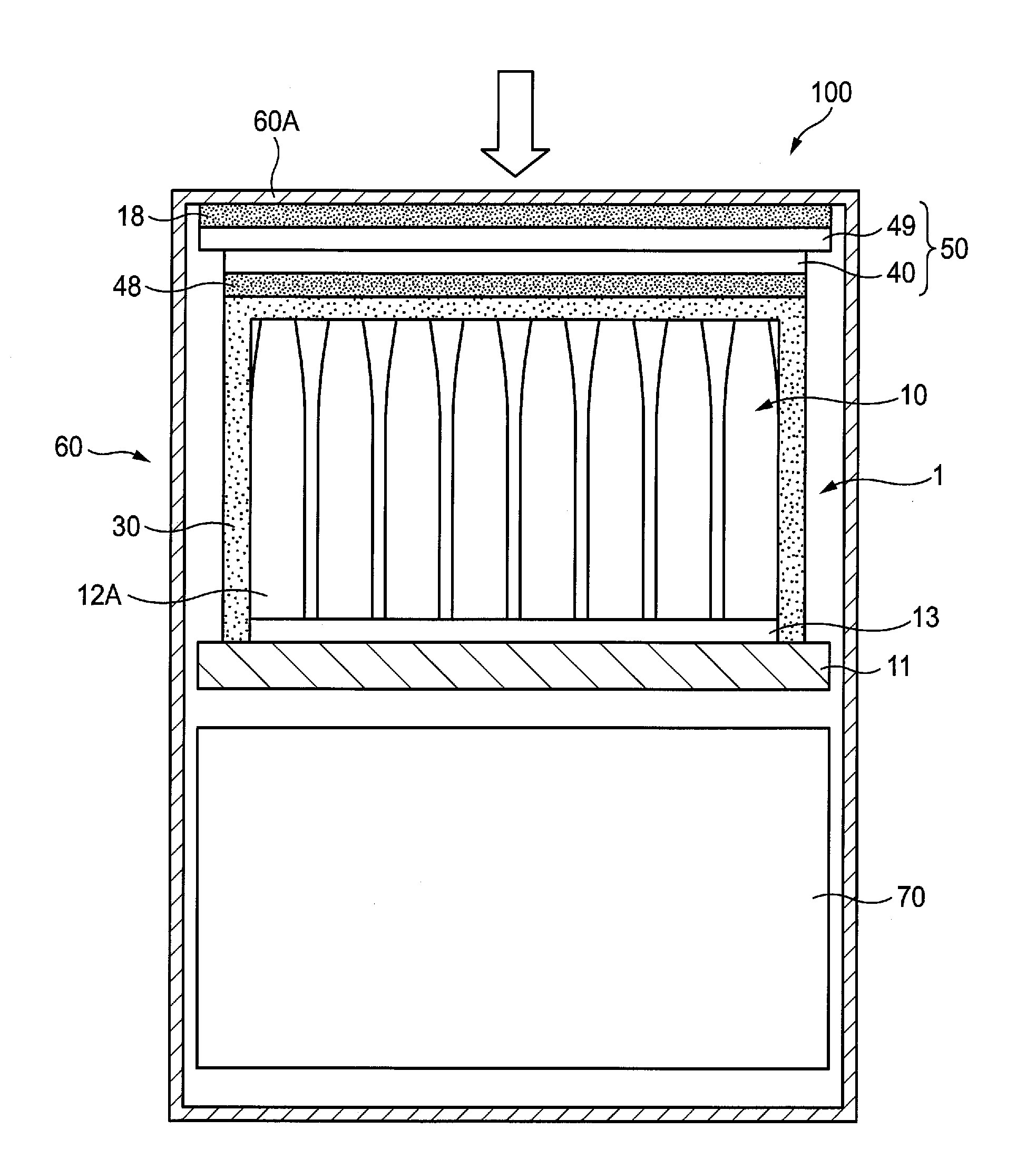
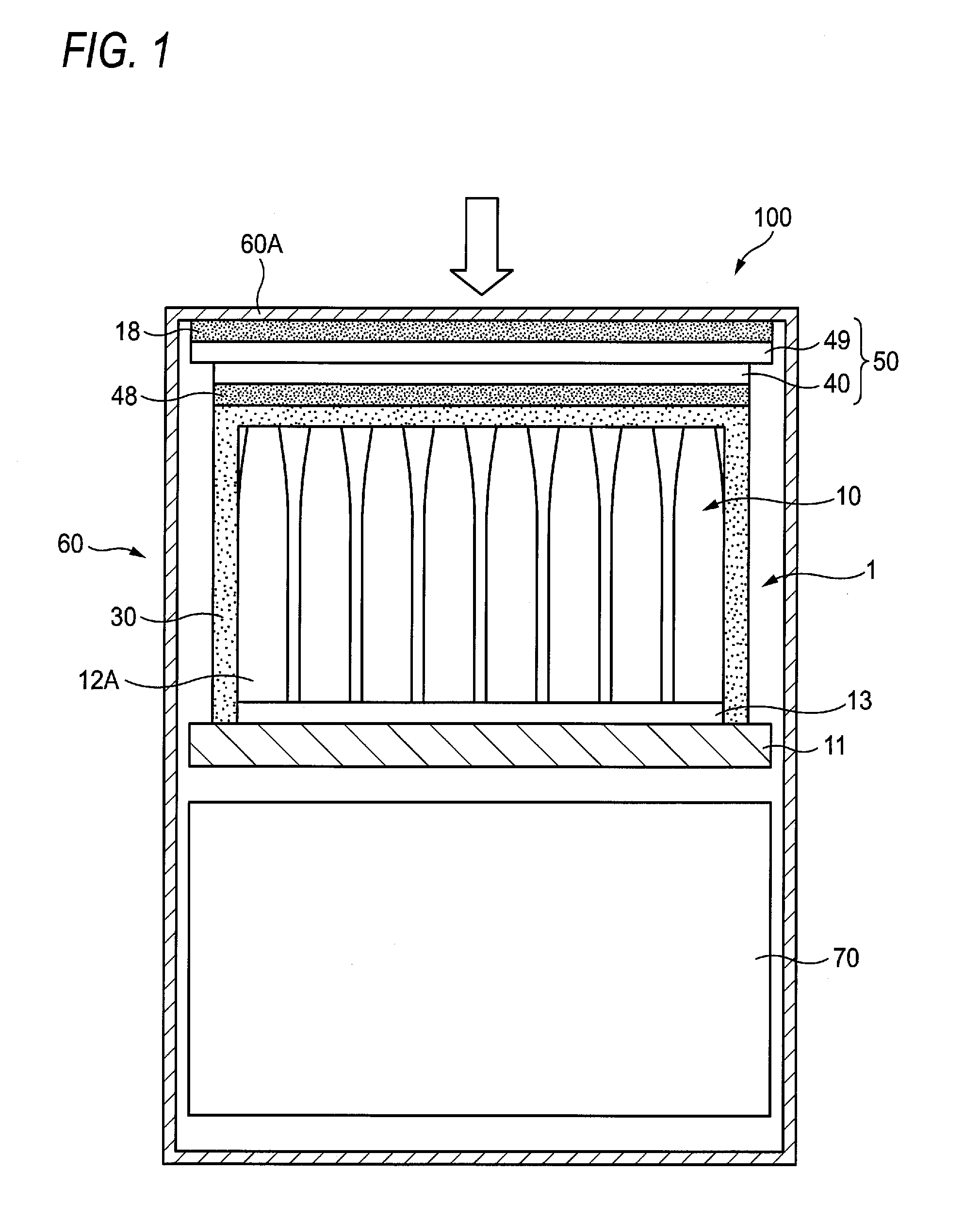
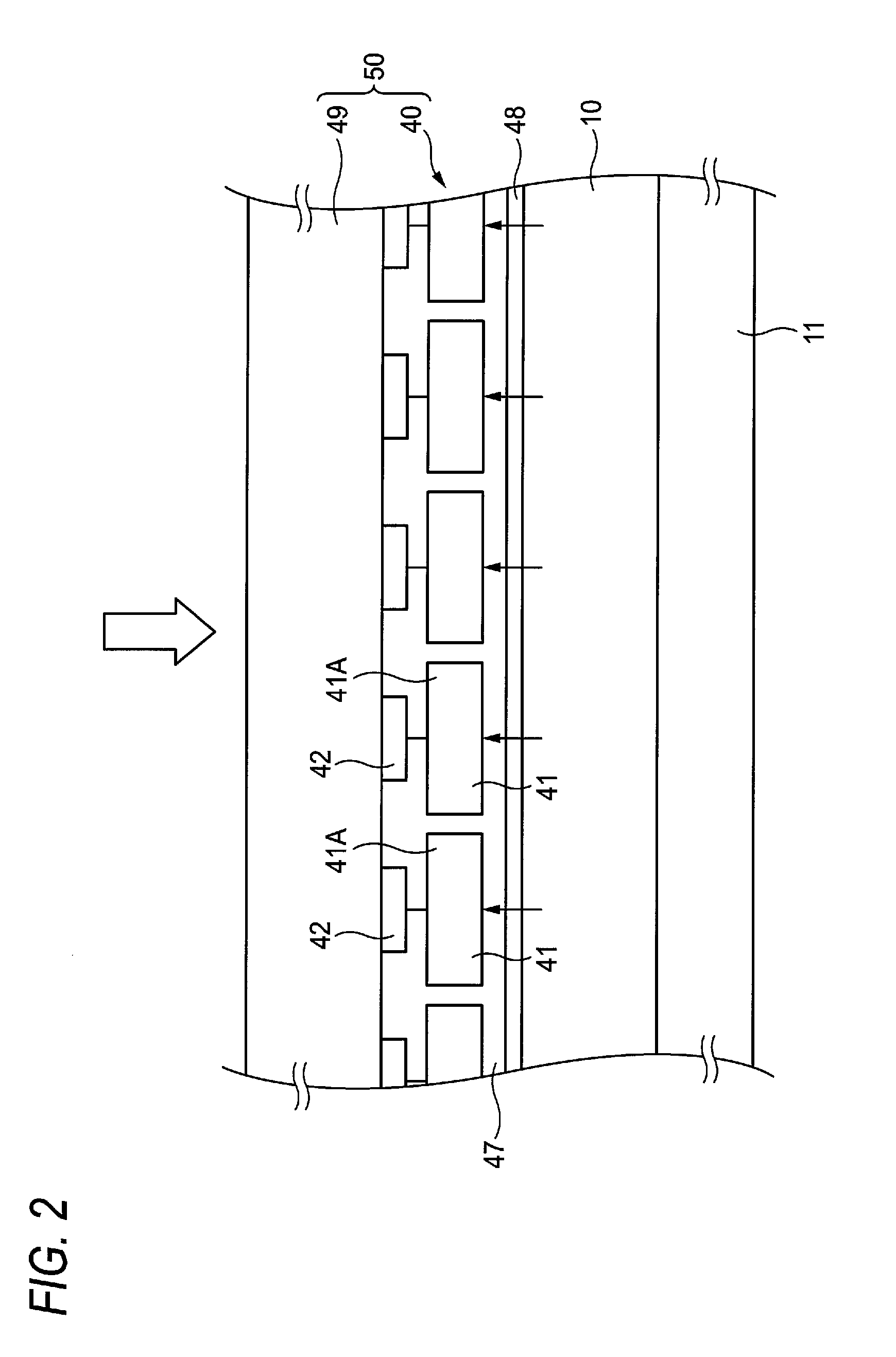
[0114]The configuration of the protective member provided in the photodetecting unit is not limited to that mentioned above. As shown in; for instance, FIG. 11, there can also be adopted a configuration including a base substance 49A (a resin layer) made of a resin and a light reflection film 49B (a light reflection layer) that is layered on an X-ray entrance side of the base substance 49A and that is made of aluminum or the like.

[0115]FIG. 12 shows an example modification of the X-ray image detection apparatus. In the example modification, after the process for peeling and removing a substrate, a protective film 35 is provided by use of; for instance, parylene, on side surfaces of the thin film portion 40, side surfaces of the protective member 49, and the peel surface of the protective member 49 facing the substrate 51. In addition to the protective film 30 provided on the scintillator 10, the thus-provided protective film 35 seals the scintillator 10 and th...


PUM


Abstract

A method of manufacturing a radiological image detection apparatus having: a scintillator that emits fluorescence upon exposure to radiation; and a photodetecting unit disposed on a radiation entrance side of the scintillator, the method includes: a photodetecting unit production process for layering on a substrate a protective member that exhibits low radiation absorbency than that exhibited by the substrate and forming a thin film portion that detects the fluorescence as an electric signal on the protective member, thereby producing the photodetecting unit; a substrate peel-removal process for peeling and eliminating the substrate from the protective member; and an integration process for integrating the previously-produced scintillator and the photodetecting unit before or after the substrate peel-removal process.

Description

CROSS-REFERENCE TO RELATED APPLICATIONS[0001]This application is based on and claims priority under 35 USC 119 from Japanese Patent Application No. 2011-038954 filed on Feb. 24, 2011; the entire content of which is incorporated herein by reference.BACKGROUND[0002]1. Technical Field[0003]The invention relates to a radiological image detection apparatus used in a medical radiological imaging system, or the like and a method of manufacturing the same.[0004]2. Related Art[0005]DR (Digital Radiography) using a radiological image detection apparatus, like an FPD (Flat Panel Detector) that converts a radiological image, such as an X-ray image, into digital data, has recently been put into practice. When compared with a related art CR (Computed Radiography) system that uses an imaging plate made of a photostimulable phosphor (an accumulative phosphor), the radiological image detection apparatus has an advantage of being able to ascertain an image immediately. Thus, the DR has become prolife...

Claims


Application Information

Patent Timeline
Patent Type & Authority Patents(United States)
IPC IPC(8): G01T1/20
CPCH01L27/14663G01T1/202
Inventor IWAKIRI, NAOTONAKATSUGAWA, HARUYASU
Owner FUJIFILM CORP
Why Eureka
Try Eureka