Techniques for multi-wire encoding with an embedded clock

a multi-wire encoding and clock technology, applied in pulse conversion, pulse technique, instruments, etc., can solve the problems of limiting the use of high-performance applications, requiring extra wires and related circuitry, and additional requirements tend to increase the complexity of laying out strobe-based memory controllers and memory devices on circuit boards

Active Publication Date: 2014-02-11
RAMBUS INC
View PDF5 Cites 131 Cited by
  • Summary
  • Abstract
  • Description
  • Claims
  • Application Information

AI Technical Summary

Problems solved by technology

Each of these known approaches has disadvantages which may limit its use in high-performance applications.
One disadvantage of the traditional strobed timing architecture lies in the requirement of extra wires and related circuitry which are dedicated to the transmission and detection of strobe signals.
This additional requirement tends to increase the complexity of laying out strobe-based memory controllers and memory devices on circuit boards.
The phase maintenance circuitry may be costly to design and consumes additional chip power.
The phase maintenance requirement may be difficult to satisfy when environmental drift components are present in the memory device to cause continual phase drifts in its local clock.
Furthermore, tracking of the phase drifts may be too slow to satisfy high-performance needs of modern data memory devices.
The 8B / 10B encoding not only leads to overhead costs, but also reduces useful bandwidth.

Method used


Image

  • Techniques for multi-wire encoding with an embedded clock
  • Techniques for multi-wire encoding with an embedded clock
  • Techniques for multi-wire encoding with an embedded clock

Examples


Embodiment Construction

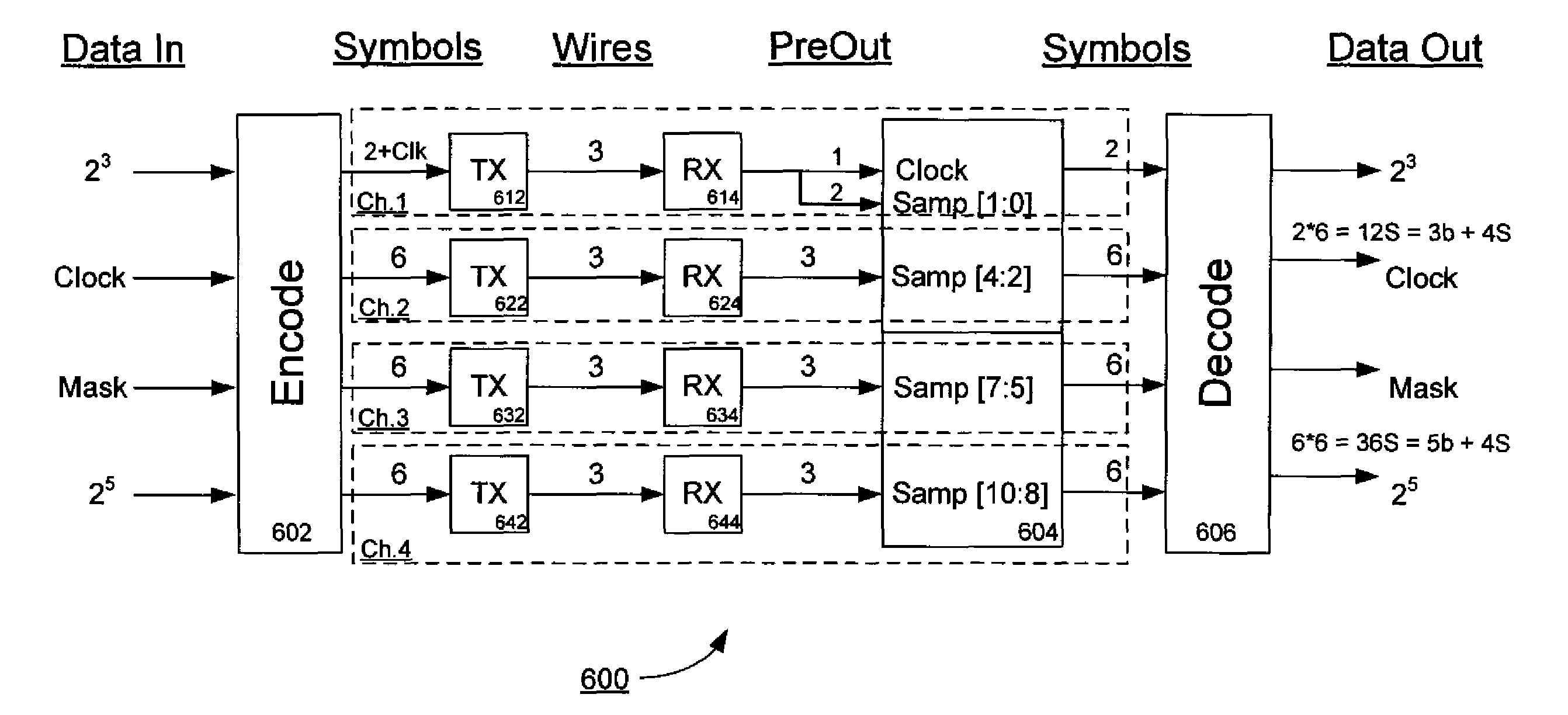
[0021]Embodiments of the present disclosure provide improved timing control techniques for data communications among electronic components. A transmitter component may encode a set of symbols according to a multi-wire encoding scheme and, with the timing control of a transmit clock, transmit the encoded symbols to a receiver component over a set of wires. The transmitter may also restrict the transmission of a first subset of the encoded symbols to a first portion of a clock cycle associated with the transmit clock and restrict the transmission of a second subset of the encoded symbols to a second portion of the clock cycle. As a result of theses restrictions, a clock signal may become embedded in the multi-wire encoded transmission. The embedded clock signal may be recovered by the receiver component and serve as a receive clock for the reception and decoding of the encoded symbols.

[0022]While most of the description that follows will focus on communications between a memory contro...


PUM


Abstract

Techniques for multi-wire encoding with an embedded clock are disclosed. In one particular exemplary embodiment, the techniques may be realized as a transmitter component. The transmitter component may comprise at least one encoder module to generate a set of symbols, each symbol being represented by a combination of signal levels on a set of wires. The transmitter component may also comprise at least one signaling module to transmit one or more of the symbols over the set of wires according to a transmit clock. The transmitter component may additionally comprise control logic to restrict transmission of first and second subsets of the set of symbols to respective first and second portions of a clock cycle of the transmit clock, such that a signal differential among at least two of the set of wires exhibits a switching behavior that has a same frequency as the transmit clock.

Description

FIELD OF THE DISCLOSURE[0001]The present disclosure relates generally to electronic devices and data communications therewith, and, more particularly, to techniques for multi-wire encoding with an embedded clock.BACKGROUND OF THE DISCLOSURE[0002]Modern memory devices, such as double data rate (DDR) and graphics double data rate (GDDR) memory devices, typically require a reliable timing control for high-speed operations. At least three types of timing control architectures are currently in use or have been proposed—strobed timing (or “source synchronous timing”), clocked timing, and clock-data-recovery or “clock and data recovery” (CDR). Each of these known approaches has disadvantages which may limit its use in high-performance applications.[0003]In a typical strobed timing architecture, a memory controller (e.g., a graphics processing unit or “GPU”) may be coupled to a DDR or GDDR memory device via a bi-directional data bus, and a pair of strobe paths may run in parallel with the d...

Claims


Application Information

Patent Timeline
Patent Type & Authority Patents(United States)
IPC IPC(8): H04L27/00
CPCG11C7/1066H03K3/356026G11C7/1093H04L25/026G11C7/222H04L25/4917G11C7/02H04L25/4906H03M5/20H04L25/0272H03M5/16G11C7/1051H03K19/01855
Inventor WARE, FREDERICKKIZER, JADE
Owner RAMBUS INC
Why Eureka
Try Eureka