System and method for closed-loop optical network power backoff

a closed-loop optical network and power backoff technology, applied in the field of communication systems, can solve the problems of bit errors, relatively high cost of retransmission, and exponentially increasing complexity, and achieve the effect of reducing power consumption and power

Active Publication Date: 2014-02-11
MACOM CONNECTIVITY SOLUTIONS LLC
View PDF15 Cites 22 Cited by
  • Summary
  • Abstract
  • Description
  • Claims
  • Application Information

AI Technical Summary

Benefits of technology

[0016]Disclosed herein are system and method to reduce the power consumed, by circuitry involved in the transmission and reception of signals. The operation can be performed by monitoring the intensity of the received optical signal or the error ratio of a converted electrical signal. Then, an in-band signal can be used to communicate the quality of the received signal, between the transmitter and receiver, so that decisions can be made as to what circuitry can be bypassed to reduce power.
[0017]There are many instances where the link attenuation is less than the specified maximum. Most instantiations are designed and implemented with the assumption of the maximum reach. By using a closed-loop power backoff, the system can monitor everything from signal light intensity to electrical signal quality and reduce the power consumption; thereby, saving the end user from paying for power that is providing no improved system performance.

Problems solved by technology

FEC is therefore applied in situations where retransmissions are relatively costly, or impossible such as when broadcasting to multiple receivers.
Viterbi decoding allows asymptotically optimal decoding efficiency with increasing constraint length of the convolutional code, but at the expense of exponentially increasing complexity.
Bit errors can occur when a (relatively) long series of 1's create a dc level that charges the capacitor of the high-pass filter used as the AC coupler, bringing the signal input down incorrectly to a 0-level.
The “cost” of dc balancing is the increase in signal overhead.
Typically, there is no means other than manual intervention or open-loop “trial-and-error” to either turn off unneeded circuitry or to reduce the number of taps in an equalizer.

Method used


Image

  • System and method for closed-loop optical network power backoff
  • System and method for closed-loop optical network power backoff
  • System and method for closed-loop optical network power backoff

Examples


Embodiment Construction

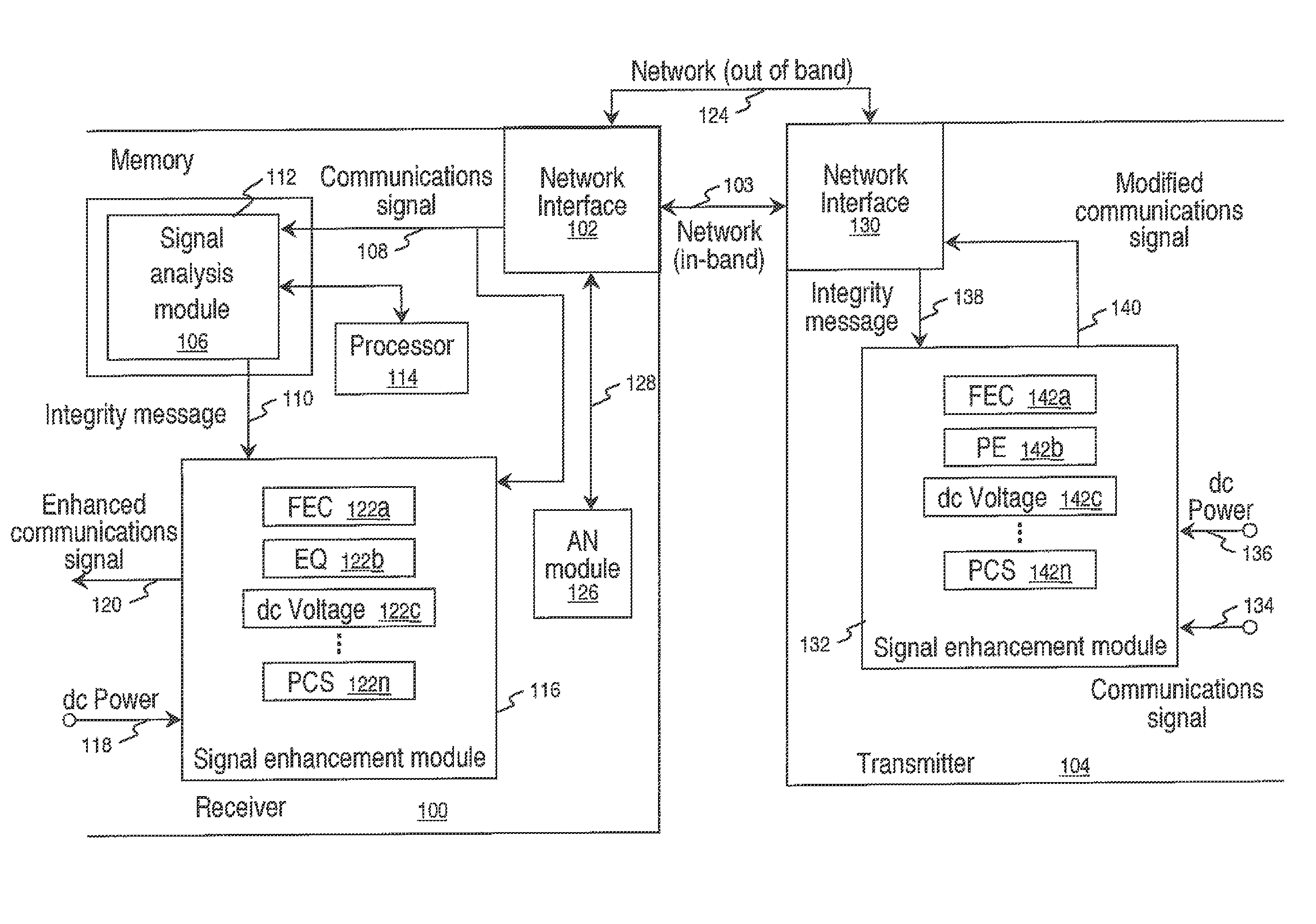
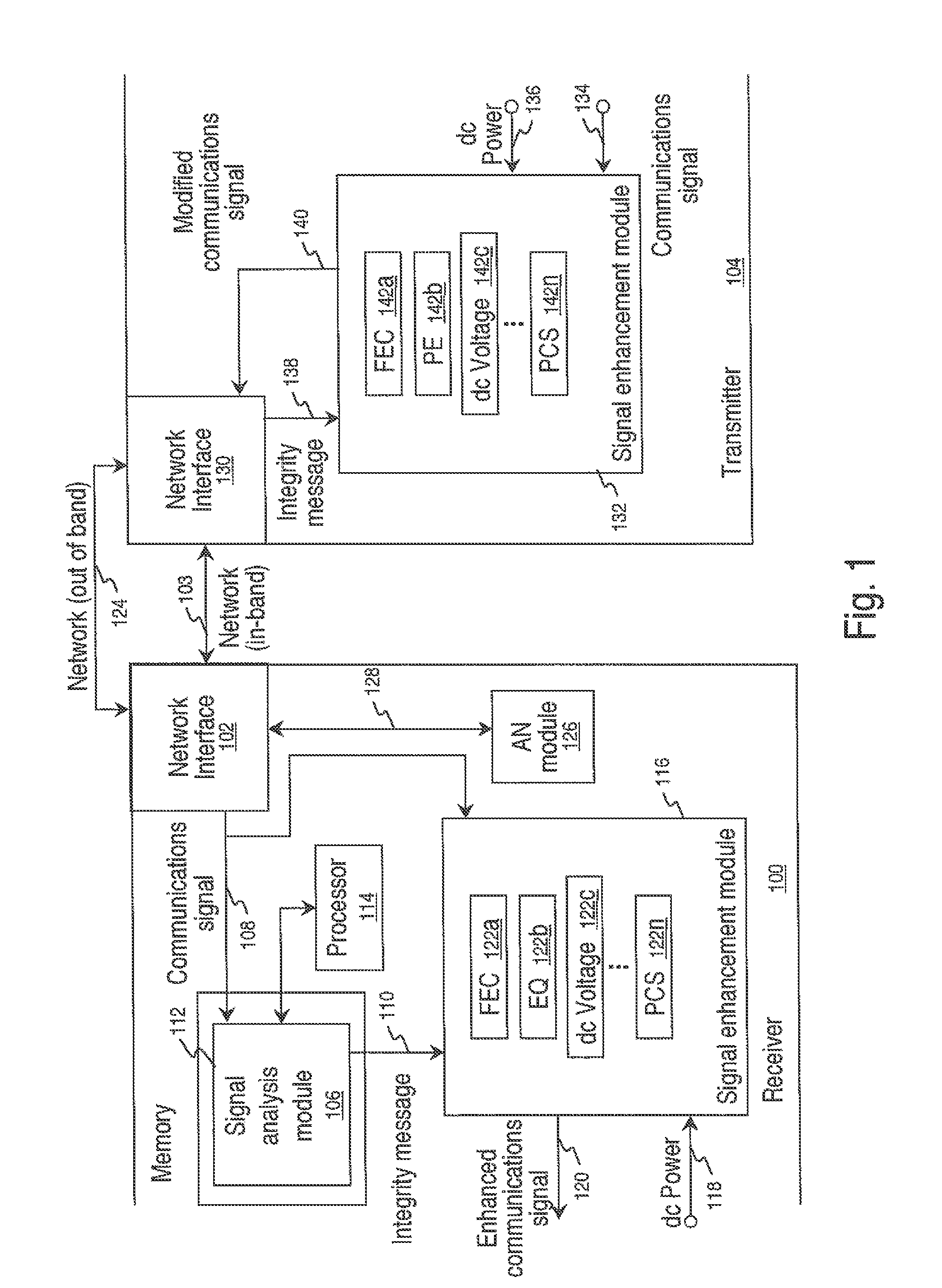
[0028]FIG. 1 is a schematic block diagram of a communication device receiver for managing a plurality of signal enhancement mechanisms. The receiver 100 comprises a network interface 102 on line 103 for accepting a communications signal from a transmitter 104. The network 103 may be a Local Area Network (LAN), such as the Ethernet, or an Optical Transport Network (OTN), such as a Synchronous Optical Network (SONET) or in accordance with ITU-T G.709. The receiver is not limited to any particular type of network or protocol.

[0029]A signal analysis module 106 has an input on line 108 to accept the communications signal. The signal analysis module 106 analyzes signal integrity and, in response, supplies an integrity message at an output on line 110. In one aspect as shown, the signal analysis module is enabled as a sequence of software instructions that are stored in a tangible memory 112 and executed by a processor 114. Alternatively, the signal analysis module 106 may be enabled in ha...


PUM


Abstract

In a communication device using a plurality of signal enhancement mechanisms, a system and method are provided for managing signal processing power consumption. A receiver accepts a communications signal and analyzes signal integrity. In response to analyzing the signal integrity, a signal enhancement mechanism is changed, and device power consumption is modified in response to changing the signal enhancement mechanism. In one aspect, the receiver changes a receiver signal enhancement mechanism, and modifies its power consumption. For example, one or more of the following receiver signal enhancement mechanisms may be selected: forward error correction (FEC), equalization, dc voltage level, and physical coding sublayer (PCS).

Description

BACKGROUND OF THE INVENTION[0001]1. Field of the Invention[0002]This invention generally relates to communication systems and, more particularly, to a system and method for adjusting signal enhancement mechanisms on the receiver and transmitter ends of a link to ensure communications while minimizing power consumption.[0003]2. Description of the Related Art[0004]As noted in Wikipedia, forward error correction (FEC) or channel coding is a system of error control for data transmission, whereby the sender adds systematically generated redundant data to its messages, also known as an error-correcting code. A carefully designed redundancy permits the receiver to detect and correct a limited number of errors occurring anywhere in the message without the need to ask the sender for additional data. FEC gives the receiver an ability to correct errors without needing a reverse channel to request retransmission of data, but this advantage is at the cost of a fixed higher forward channel bandwi...

Claims


Application Information

Patent Timeline
Patent Type & Authority Patents(United States)
IPC IPC(8): H04B10/00H04B1/40
CPCH04B10/00H04L1/0009H04B1/40H04L1/0036H04B10/25H04L1/0053H04B10/0795
Inventor BOOTH, BRADLEY, JOHN
Owner MACOM CONNECTIVITY SOLUTIONS LLC
Why Eureka
Try Eureka