Laser operating process and laser device

a laser treatment and laser technology, applied in laser beam welding equipment, welding equipment, metal-working equipment, etc., can solve the problem of difficult continuous monitoring of the process during laser treatmen

Inactive Publication Date: 2014-02-18
LEISTER TECHNOLOGIES
View PDF19 Cites 10 Cited by
  • Summary
  • Abstract
  • Description
  • Claims
  • Application Information

AI Technical Summary

Benefits of technology

[0022]For example, if a liquid crystal phase modulator is used as a variable DOE, it changes, starting from a polarized radiation field with sufficient transversal coherence, the phase relationship of individual sub-ranges of the arriving laser beams in a controlled manner so that the sub-ranges interfere in the desired manner after the diffractive optical element. The liquid crystal cells divide the arriving laser beam into individual bundles of sub-beams. Each of the bundles of sub-beams is phase-modulated in a certain way in the individually controllable cells. After leaving the DOE, the individual sub-beams in their entirety form a new laser beam. Here, the modulation of a bundle of sub-beams that is determined by the associated liquid crystal cell is performed in an especially simple and flexible manner and, particularly, independent of the other bundles of sub-beams.
[0024]Every laser beam emitted by a laser source has a certain convergence, i.e. an expansion that increases with distance after the beam exits from the laser source, which represents a measure of the beam quality. The low convergence of the pilot laser beam and of the effective laser beam before the diffractive optical element, that may also be different, is influenced by the diffraction and the phase modulation on the DOE so that after the DOE, the laser beams of the pilot target laser and of the effective power laser propagate spatially in the desired manner. Due to the different wavelengths of the pilot laser beam and of the effective laser beam, their expansion after the diffractive optical element is different, causing the pilot laser beam and the effective laser beam to produce beam patterns of different sizes on the work pieces.
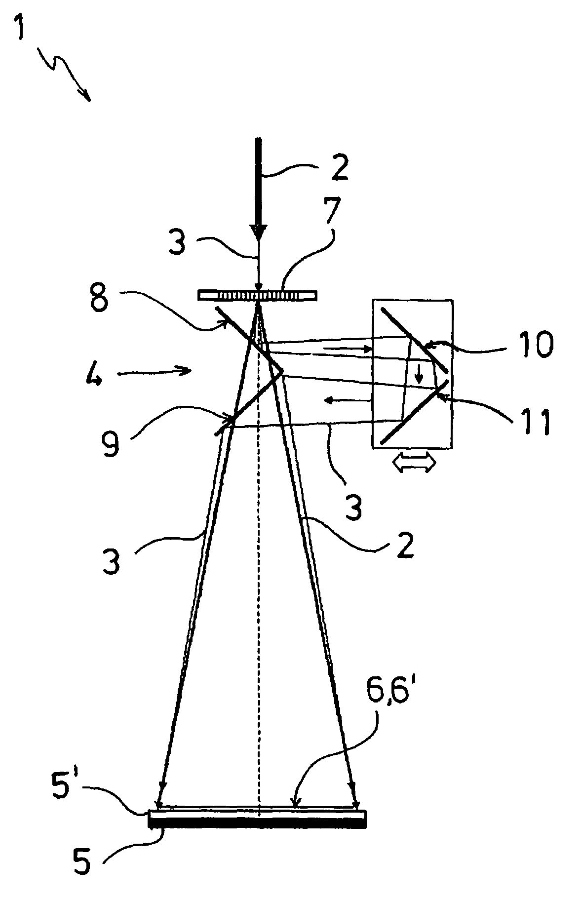
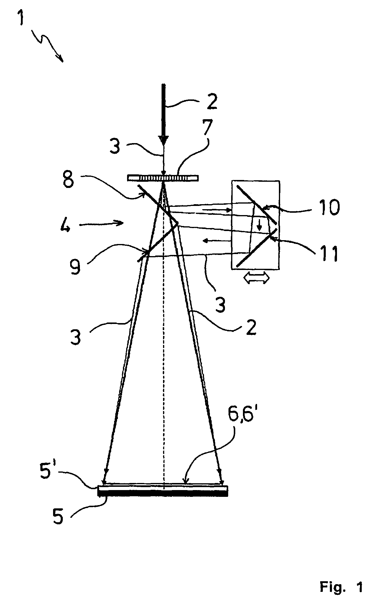
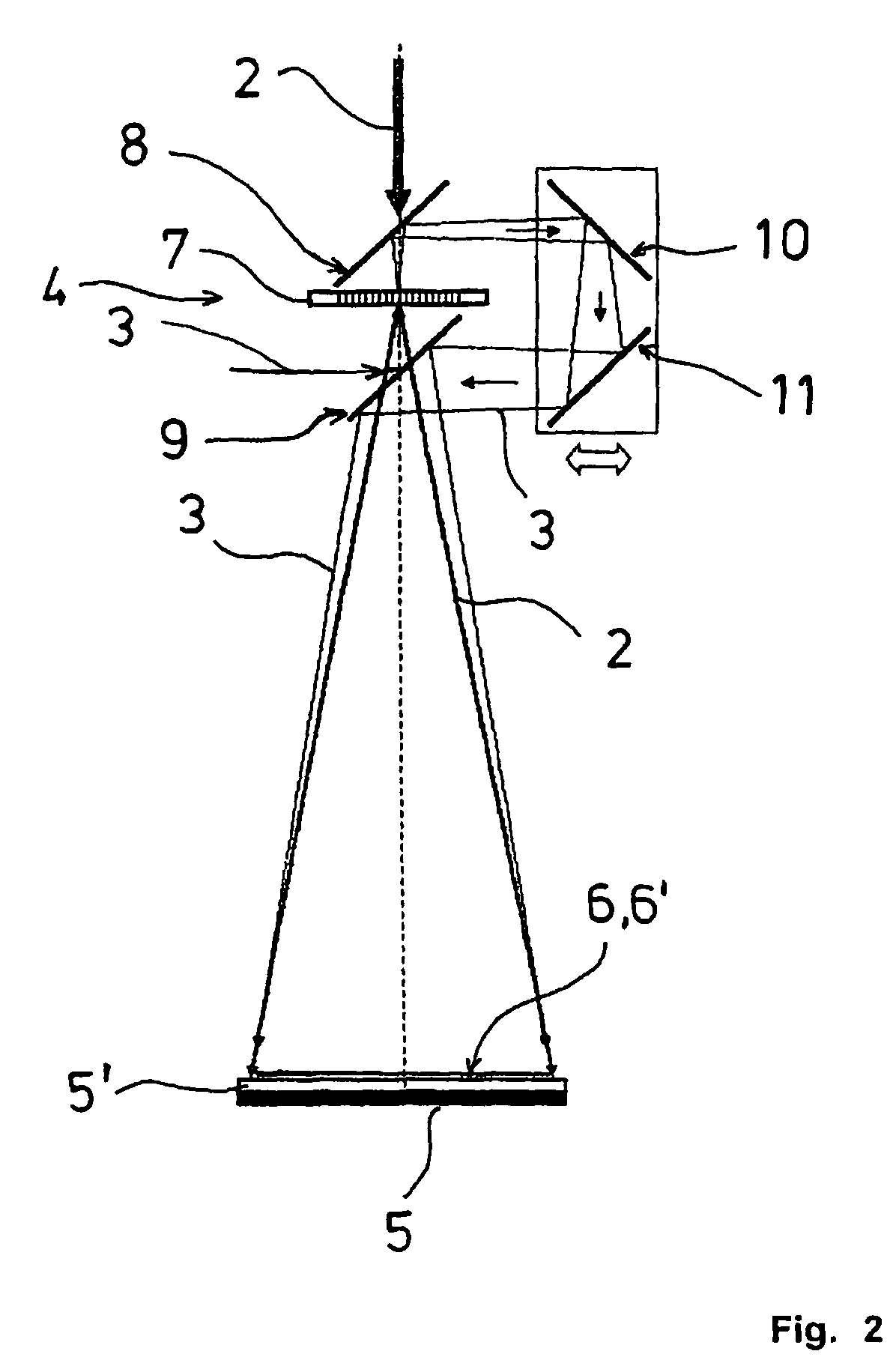
[0029]The two deflecting mirrors act together with the two wavelength-dependent mirrors and, according to one embodiment, with a wavelength-dependent mirror and the DOE, and expand the pilot laser beam variably between the beam removal location and the re-introduction location of the laser optics by extending the path length between the DOE and the work pieces in relation to the direct path length. The smaller deflection angle of the pilot laser beam in comparison with the larger deflection angle of the effective laser beam is compensated by the circumstance that, additionally, the beam cross-section of the pilot laser beam enlarges on the extended path length due to its divergence. The distance of the two beam expansion elements from the beam deflection elements can be adjusted so that the length of the path for the pilot laser beam is variable, thereby permitting the size of the beam pattern of the pilot laser beam on the work pieces to be matched to the size of the beam pattern of the effective laser beam.
[0032]Depending on how different the two DOEs are designed, the expansion of the target laser beam compared with the effective laser beam is more or less pronounced. Here, a precise adjustment of the DOE in question to the wavelength of the effective power laser or of the pilot target laser has the effect that the effective laser beam and the pilot laser beam exit from the DOE with the same beam cross-section. In this case, a beam expansion system after the DOEs is not required for imaging the beam patterns superimposed with identical position, form, and size on the work pieces.

Problems solved by technology

The selection of the desired beam spot and the exact positioning of the beam spot in relation to the work pieces, in order to act thereon either at a certain point at a certain location or along a pre-selected line by means of the effective laser beam, frequently causes problems because the laser light of the effective power laser is usually not visible, or only visible with great difficulty.
Beside the setting-up process of the laser device, this is also true for the laser processing of the work pieces, thereby making continual monitoring of the process during the laser treatment difficult.

Method used


Image

  • Laser operating process and laser device
  • Laser operating process and laser device
  • Laser operating process and laser device

Examples


third embodiment

[0046]FIG. 3 shows a third embodiment according to the invention where the DOE 7 is operated in reflection mode for the pilot laser beam 3 and the effective laser beam 2. In the laser optics 4, the dichroic mirrors 8, 9 and the deflecting mirrors 10, 11 are arranged opposite the work pieces 5, 5′ exactly as in FIG. 1. However, after exiting from the laser sources, the laser beams 2, 3 run parallel to each other and perpendicular to the optical axis of the laser optics 4. They arrive at the DOE 7 from the same side and are jointly reflected by the DOE in the direction of the first dichroic mirror 8. For this purpose, the DOE 7 is arranged with an inclination of 45 degrees relative to the optical axis of the laser optics 4. The further propagation of the two laser beams 2, 3 after the DOE 7 corresponds to the path described in FIG. 1, with the beam expansion of the pilot laser beam 3 being performed in an analogous way.

fourth embodiment

[0047]FIG. 4 shows the laser device according to the invention that essentially corresponds to the embodiment shown in FIG. 3. After exiting from the laser sources, the laser beams 2, 3 propagate parallel to each other and perpendicular to the optical axis of the laser optics 4, arriving at the laser optics 4 between the dichroic mirrors 8, 9 and the work pieces 5, 5′. By means of a mirror element 12 with total reflection, they are deflected towards the DOE 7, past the dichroic mirrors 8, 9 and the deflecting mirrors 10, 11. The DOE 7 reflects the pilot laser beam 3 and the effective laser beam 2 in the direction of the first dichroic mirror 8. The subsequent expansion of the pilot laser beam 3 is performed as in the embodiments 1, 3 described above.

[0048]FIG. 5 shows another embodiment of the invention where the DOE 7 is also used in reflection mode for the two laser beams 2, 3. It differs from the embodiment shown and described in FIG. 3 in that the first wavelength-independent de...


PUM

PropertyMeasurementUnit
angleaaaaaaaaaa
angleaaaaaaaaaa
wavelengthsaaaaaaaaaa

Abstract

A device and a process for processing and / or joining work pieces via laser radiation, with an effective power laser and a pilot target laser that emit laser beams of different wavelengths, with the laser beams being directed at the work pieces by laser optics. Regarding the laser beams, by the laser optics that comprise at least one diffractive optical element (DOE) as a masking system, the beam pattern of the pilot target laser is adjusted to match the beam pattern of the effective laser beam. This is accomplished preferably by removing the pilot laser beam from the effective laser beam for part of the path length by dichroic mirrors, and by expanding the diverging pilot laser beam on said part of the path length by deflecting mirrors whose distance from the dichroic mirrors is variable.

Description

CROSS-REFERENCE TO RELATED APPLICATION[0001]The present application claims priority under 35 USC §119 to European Patent Application No. 08 008 336.3, filed on May 2, 2008, the entire disclosure of which is incorporated herein by reference.TECHNICAL FIELD OF THE INVENTION[0002]The invention concerns a process for processing and / or joining work pieces by means of laser radiation, with an effective power laser and a pilot target laser that emit an effective laser beam and a pilot laser beam of different wavelengths, with the laser beams being directed at the work pieces by means of laser optics, and with the laser beams of the effective laser and of the pilot target laser being imaged on the work pieces with randomly selectable beam patterns that are superimposed and identical in terms of position and form. The invention also concerns a laser device for performing the proposed process. The pilot target laser is a laser emitting in the visible spectral range that simplifies the set-up ...

Claims


Application Information

Patent Timeline
Patent Type & Authority Patents(United States)
IPC IPC(8): B23K26/20B23K26/04B23K26/36
CPCB23K26/0656B23K26/0604B23K26/066
Inventor GUBLER, ULRICHSCHEIDT, MICHAEL
Owner LEISTER TECHNOLOGIES
Why Eureka
Try Eureka