Window defroster assembly having transparent conductive layer

a technology of transparent conductive layer and defroster, which is applied in the direction of ohmic resistance heating, heater elements, transportation and packaging, etc., can solve the problems of limited ability of plastics to conduct heat, defroster or defogger, and windows are not without limitations, so as to increase the spacing of the grid

Inactive Publication Date: 2014-02-18
EXATEC LLC
View PDF42 Cites 9 Cited by
  • Summary
  • Abstract
  • Description
  • Claims
  • Application Information

AI Technical Summary

Benefits of technology

[0011]The present invention provides a heater grid capable of defrosting the viewing area of a window in a manner that emulates the performance of a conventional heater grid on a glass window. The present invention allows the spacing between grid lines to be greater than the conventional spacing of 25-30 mm currently used for heater grids on glass windows. Due to its performance on a plastic panel window, the heater grid of the present invention is anticipated as being usable to increase the grid line spacing for a heater grid applied on a glass panel or window.
[0015]In another embodiment, the present invention provides a window assembly as described above, with a protective coating. The protective coating may further comprise a plurality of coatings provided in a layered structure to enhance protection against weathering and abrasion.

Problems solved by technology

Although there are many advantages associated with implementing plastic windows, these windows are not without limitations that represent technical hurdles that must be addressed prior to wide-scale commercial utilization.
Limitations relating to material properties include the stability of plastics during prolonged exposure to elevated temperatures and the limited ability of plastics to conduct heat.
Thus, a defroster or defogger (hereafter just “defroster”) designed to work effectively on a glass window may not necessarily be efficient at defrosting or defogging (hereafter just “defrosting” or “defrost”) a plastic window.
The lower thermal conductivity of the plastic may limit the dissipation of heat from the heater grid lines across the surface of the plastic window.
This difference in conductivity manifests itself in poor defrosting characteristics exhibited by the plastic window, as compared to the glass window.

Method used


Image

  • Window defroster assembly having transparent conductive layer
  • Window defroster assembly having transparent conductive layer
  • Window defroster assembly having transparent conductive layer

Examples


Embodiment Construction

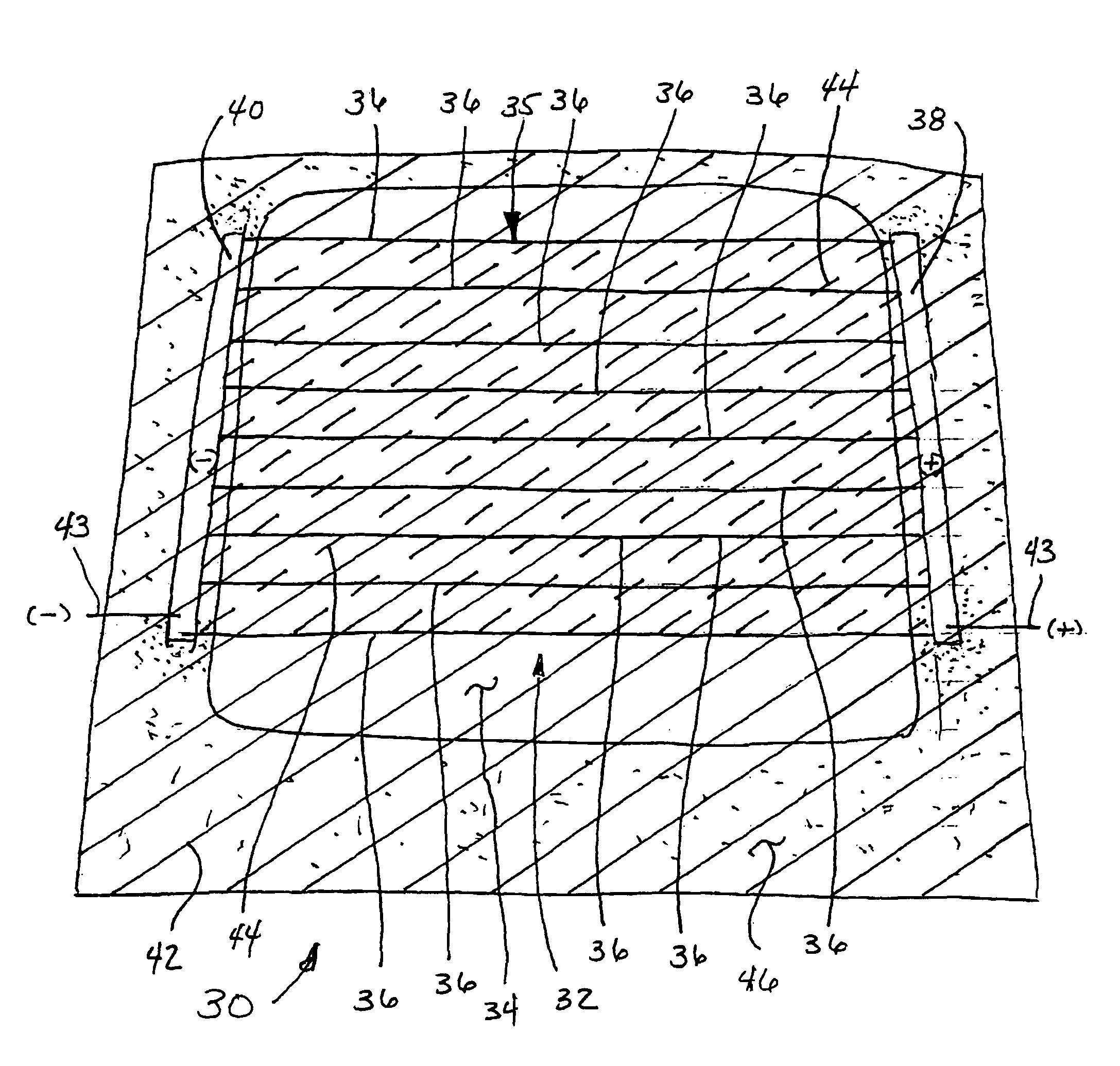
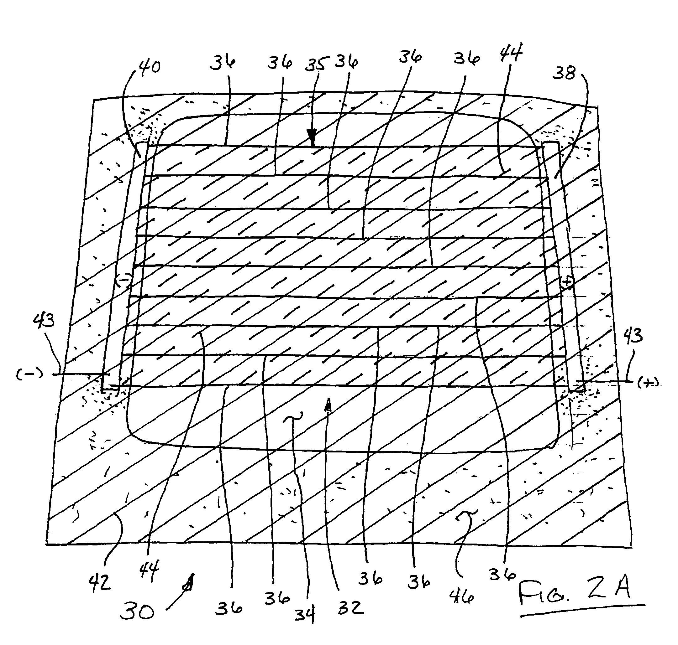
[0020]The following description of the preferred embodiment is merely exemplary in nature and is in no way intended to limit the invention or its application or uses.

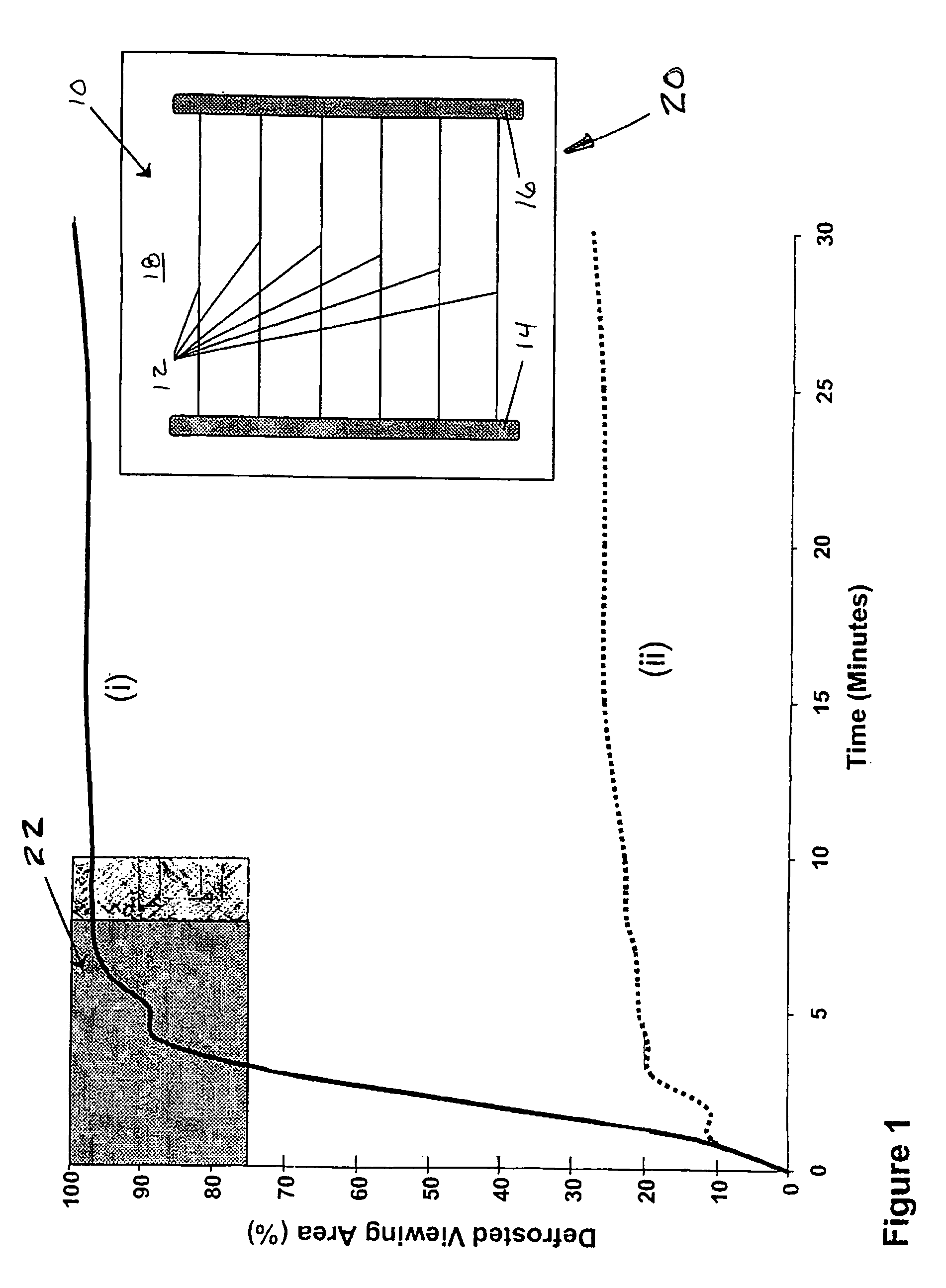
[0021]The inventors have observed that a conventional heater grid or defroster formed on a plastic panel (using a metallic ink and subsequently cured according to the manufacturer's recommendations) performs poorly in industry standardized defroster tests established for the evaluation of a heater grid on a glass window. The test protocol for the automotive industry requires that at least 75% of the visual area be defrosted within a 30 minute time frame. This protocol, however, is considerably slower than the results typically seen for a glass window. In order for a defroster formed on a plastic panel to achieve performance similar to a defroster formed on glass, the heater grid must actually defrost at least 75% of the viewing area in less than about ten minutes. The test protocol utilized to characterize window defros...


PUM


Abstract

A window defroster assembly having a transparent panel and a defroster. The defroster includes a conductive layer applied over the panel and an electrically conductive heater grid formed integrally with the transparent panel. The heater grid includes a series of grid lines and at least a portion of the conductive layer is located between adjacent ones of the grid lines.

Description

CROSS REFERENCE TO RELATED APPLICATION[0001]This application is a continuation-in-part of prior application Ser. No. 10 / 847,250 filed May 17, 2004, the entire contents of which are hereby incorporated by reference.BACKGROUND[0002]1. Field of the Invention[0003]This invention relates to a conductive heater grid design that provides performance characteristics making it amenable for use in defrosting plastic and glass panels, such as windows in vehicles.[0004]2. Related Technology[0005]Plastic materials, such as polycarbonate (PC) and polymethylmethyacrylate (PMMA), are currently being used in the manufacturing of numerous automotive parts and components, such as B-pillars, headlamps, and sunroofs. Automotive rear window (backlight) systems represent an application for these plastic materials due to their many identified advantages, particularly in the areas of styling / design, weight savings, and safety / security. More specifically, plastic materials offer the automotive manufacturer t...

Claims


Application Information

Patent Timeline
Patent Type & Authority Patents(United States)
IPC IPC(8): H05B3/06B60L1/02H05B11/00H05B3/16H05B3/84H05B3/00H05B1/00H05B3/02
CPCH05B2203/013H05B2214/04H05B3/84H05B2203/002
Inventor WEISS, KEITH, D.
Owner EXATEC LLC
Why Eureka
Try Eureka