
Method and assembly for correcting a relaxation map for medical imaging applications

a relaxation map and imaging application technology, applied in the field of medical imaging, can solve the problems of estimating the relaxation map, signal has no, scanner renders both options unfeasible,

Inactive Publication Date: 2014-02-18
IMINDS +1
View PDF10 Cites 4 Cited by
  • Summary
  • Abstract
  • Description
  • Claims
  • Application Information

AI Technical Summary

Benefits of technology

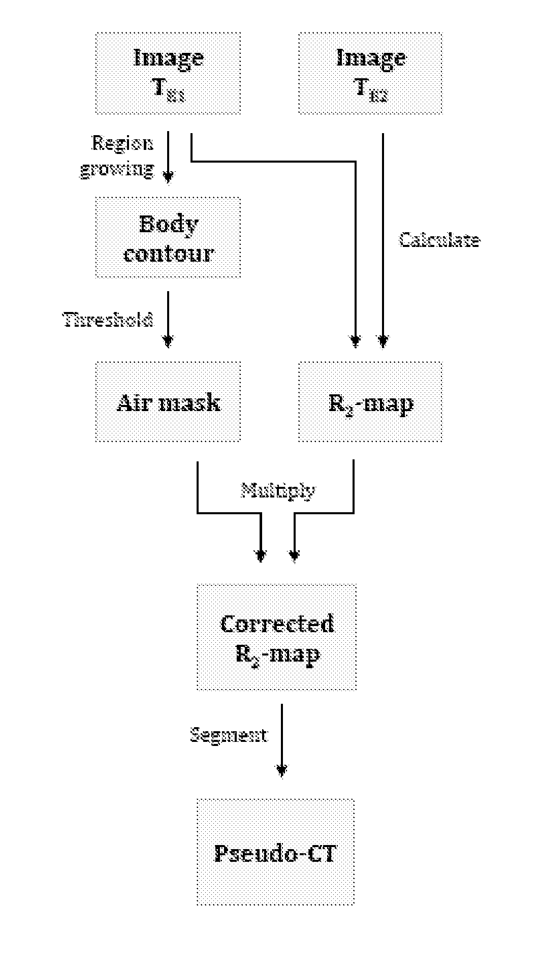
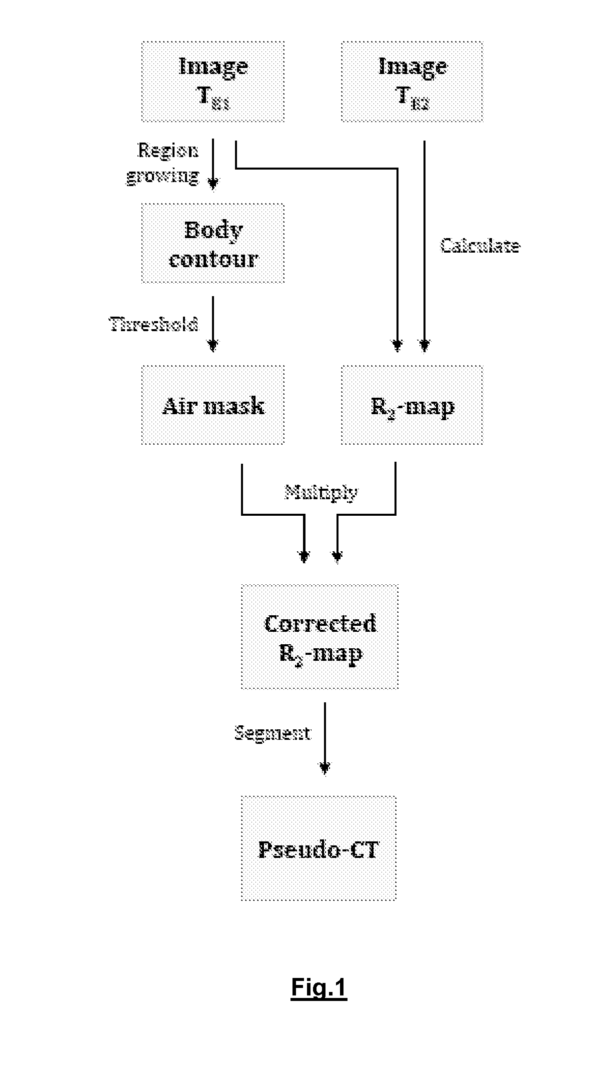
[0016]The present invention proposes to use the quantitative parameter R2, the transverse relaxation rate in order to achieve the above-mentioned goal. Consequently, the invention relates in a first aspect to method for correcting a relaxation map of an object scanned with a MR imaging modality like, whereby that object comprises a plurality of structure and / or tissue types. The object is typically a (part of a) tissue or an organ. A first estimate of a relaxation map of the scanned object is derived from at least two 3D scans acquired by applying a sequence of pulses adapted for distinguishing between the various structure and / or tissue types. The use of an ultrashort echo time (UTE) pulse sequence indeed allows distinguishing between the various structure and / or tissue types present in the scanned object, like e.g. bone, soft tissue and air. In a next step information is obtained on the content of voxels, i.e. the type of structure and / or tissue type, present in the first estimate of the relaxation map. The obtained information is translated into a binary mask. By combining that binarized information with the first estimate of the relaxation, a corrected estimate of the relaxation map is obtained.
[0019]In another embodiment of the invention a filtering (smoothing) operation is performed on at least one of the acquired scans. This allows reducing certain artefacts or noise in the echo images.

Problems solved by technology

One of the difficulties in designing a multimodality PET-MR scanner is the derivation of that attenuation map to correct the PET image for said attenuation.
The small space available inside the bore of a MR scanner renders both options unfeasible.
The implicit difficulty in estimating the attenuation map from MR images is that the MR signal has no direct correlation with tissue density, as MR sequences only measure the relaxation of proton spins in a high magnetic field.
The challenge in MR based attenuation correction is finding a way to determine tissue density based on information that bears no direct correlation with this characteristic.
However, the very low signal intensity of cortical bone in images acquired with conventional MR sequences makes it difficult to distinguish this tissue type from air, while cortical bone has an attenuation coefficient strongly different from air.
There lies the vulnerability of these methods in clinical practice, since there can be a lot of variability in patient anatomy.
However, an important drawback of the proposed method is that the attenuation map is derived by using thresholds on the image intensity of the long and short echo image acquired with the UTE sequence.
As image intensity in MR is not a stable, quantitative measure (it depends on receiver gain settings etc.), this method would be difficult to implement on a large scale as the thresholds would have to be reconfigured for each imaging session.

Method used


Image

  • Method and assembly for correcting a relaxation map for medical imaging applications
  • Method and assembly for correcting a relaxation map for medical imaging applications
  • Method and assembly for correcting a relaxation map for medical imaging applications

Examples


Embodiment Construction

[0029]In order to allow the use of the quantitative transverse relaxation rate parameter to derive a density image, the invention discloses in one aspect a technique for correcting a rough first estimation of a relaxation map derived from at least two three-dimensional images of a medical imaging modality like e.g. MR. Suitable sequences, namely UTE pulse sequences, and image processing techniques are applied to said images to create contrast between various tissue types, e.g. air, soft tissue and cortical bone, based solely on images acquired from the patient. This renders the use of anatomical reference data obsolete.

[0030]The low signal intensity of cortical bone in conventional magnetic resonance imaging (MRI), and hence the low contrast between air and cortical bone, is caused by the lower water content of this tissue compared to soft tissue and the very fast transverse relaxation (short T2 relaxation time). Because the relaxation of protons in cortical bone occurs too fast, th...


PUM


Abstract

A method for correcting a relaxation map of an object scanned with a magnetic resonance imaging modality the object having a plurality of structure and / or tissue types. The method includes deriving a first relaxation map of a scanned object from at least two three-dimensional scans of the object acquired using a sequence of ultrashort echo time pulses adapted for distinguishing between the various types of a plurality of structure and / or tissue types of the object. Information is obtained on the type of structure and / or tissue type present in voxels in the first relaxation map and binarizing the obtained information. A corrected relaxation map is generated by combining the binarized information with the first relaxation map.

Description

CROSS-REFERENCE TO RELATED APPLICATION[0001]This application is the U.S. national phase of PCT Appln. No. PCT / EP2010 / 051868 filed Feb. 15, 2010, which claims priority to European application 09153351.3 filed Feb. 20, 2009, the disclosures of which are incorporated in their entirety by reference herein.FIELD OF THE INVENTION[0002]The present invention generally relates to the field of medical imaging. More in particular, it relates to the field of correcting a relaxation map of an object scanned with a medical imaging modality, as used in applications like attenuation or scatter correction.BACKGROUND OF THE INVENTION[0003]A new generation of medical imaging scanners is currently being developed, which combines the high sensitivity of functional imaging by positron emission tomography (PET) with the wide range of imaging and other applications of magnetic resonance (MR) scanners. This new type of scanners not only enables physicians to acquire anatomical data without any extra radiati...

Claims


Application Information

Patent Timeline
Patent Type & Authority Patents(United States)
IPC IPC(8): G06K9/00
CPCG01R33/4816G01R33/4808G01R33/4828G01R33/5615G01R33/481G01R33/50G01R33/5608
Inventor KEEREMAN, VINCENTVANDENBERGHE, STEFAANDE DEENE, YVES
Owner IMINDS
Learn More