Downdraft gasifier with internal cyclonic combustion chamber

a gasifier and cyclonic combustion technology, which is applied in the direction of combustible gas production, combustion types, lighting and heating apparatus, etc., can solve the problems of affecting the gas output, unacceptably high levels of undesirables, and the inability to gasify raw biomass optimally

Active Publication Date: 2014-02-25
BOARD OF REGENTS FOR OKLAHOMA STATE UNIVERSITY
View PDF9 Cites 3 Cited by
  • Summary
  • Abstract
  • Description
  • Claims
  • Application Information

AI Technical Summary

Problems solved by technology

Improper handling and processing of the biomass can result in a suboptimal amount of the raw biomass being gasified.
Unacceptably high levels of undesirables can also be produced and taint the output gases if the production process is not controlled.

Method used


Image

  • Downdraft gasifier with internal cyclonic combustion chamber
  • Downdraft gasifier with internal cyclonic combustion chamber
  • Downdraft gasifier with internal cyclonic combustion chamber

Examples


Embodiment Construction

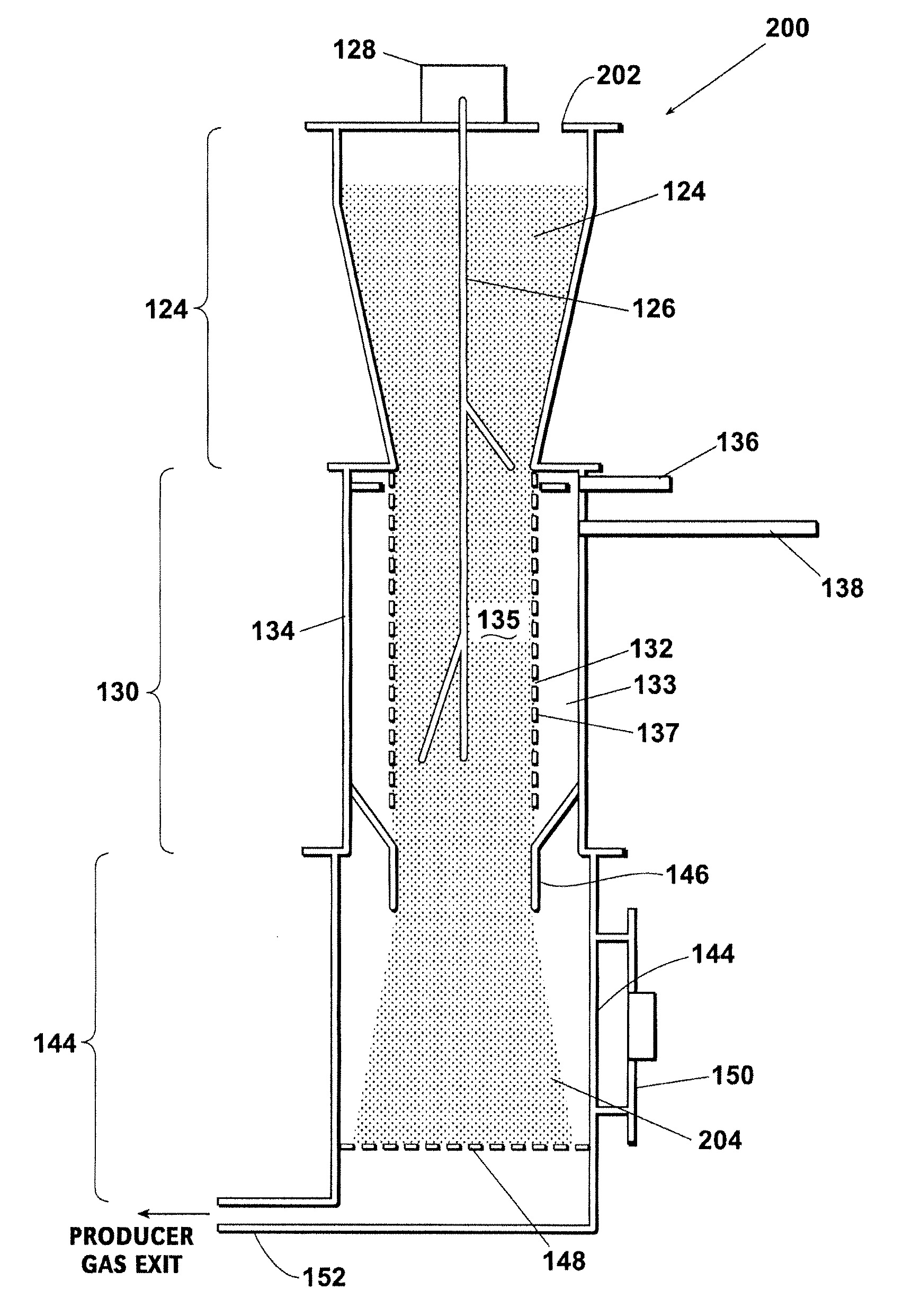
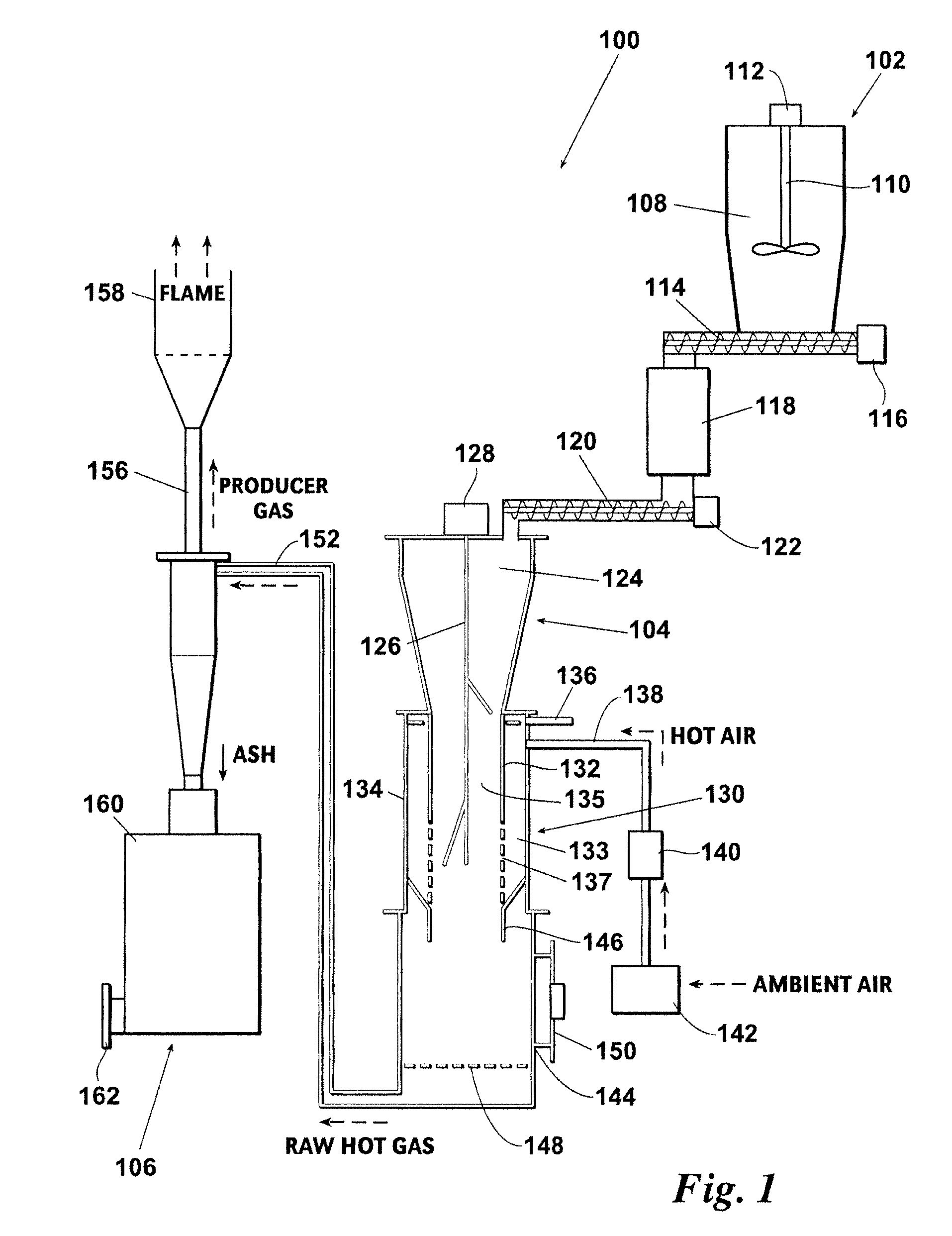
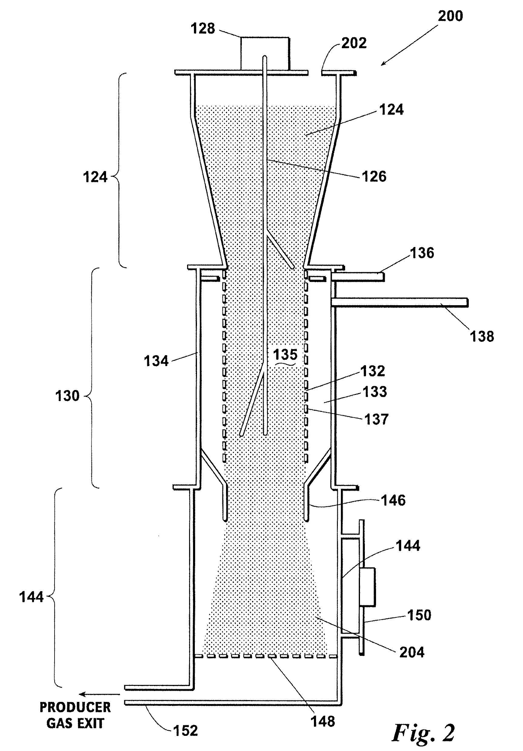
[0018]Referring now to FIG. 1, a schematic diagram illustrating one embodiment of a gasification system according to aspects of the present disclosure is shown. The gasifier system 100 comprises three primary components: a biomass feeding unit 102; a combustion chamber 104; and a separator 106. These primary components may further comprise a number of subcomponents, which will be described in detail below. The system 100 is operable to accept biomass as an input product and provide useful gases as an output product. The producer gas may be a mixture of carbon monoxide (CO), carbon dioxide (CO2), hydrogen (H2), and possibly other gases. In one embodiment, the gasification system 100 operates to convert biomass material into the desired gases by means of pyrolysis and tar cracking. This result may be achieved by creating high temperatures within the combustion chamber 104. This causes the biomass material to break down into a number of materials, including ash and gases.

[0019]The biom...


PUM

PropertyMeasurementUnit
thicknessaaaaaaaaaa
temperaturesaaaaaaaaaa
timeaaaaaaaaaa

Abstract

A downdraft gasifier is disclosed. The gasifier includes a biomass section that accepts and stirs raw biomass materials, a pyrolysis and tar cracking section having an inner cylinder for receiving biomass and an outer surrounding cylinder for gases from the biomass, and a char gasification section for receiving biomass and gases from the pyrolysis and tar cracking section. The char gasification section provides a grating and scraper for passing gases and ash and retaining biomass for char gasification on the grate.

Description

CROSS-REFERENCE TO RELATED APPLICATIONS[0001]This application is a continuation-in-part of U.S. patent application Ser. No. 11 / 773,617, entitled “DOWNDRAFT GASIFIER WITH INTERNAL CYCLONIC COMBUSTION CHAMBER”, filed Jul. 5, 2007.[0002]This application claims the priority of U.S. Provisional Patent Application No. 61 / 076,180, entitled “GASIFICATION OF SWITCHGRASS USING A DOWNDRAFT REACTOR,” filed Jun. 27, 2008, the contents of which are hereby incorporated by reference.STATEMENT REGARDING FEDERALLY SPONSORED RESEARCH OR DEVELOPMENT[0003]This invention was made with U.S. Government support under USDA / CSREES Grant No. 00-52104-9662, USDA / CSREES Grant No. 2001-34447-10302, USDA / CSREES Grant No. 2002-34447-11908, USDA / CSREES Grant No. 2003-34447-13162, USDA / CSREES Grant No. 2004-34447-14487, USDA / CSREES Grant No. 2005-34447-15711, USDA / CSREES Grant No. 2006-34447-16939, and USDA / CSREES Grant No. 2008-34447-19201 awarded by the Department of Agriculture and under DOT / OST Grant No. DTOS59-0...

Claims


Application Information

Patent Timeline
Patent Type & Authority Patents(United States)
IPC IPC(8): C10J3/08C10J1/213
CPCF23G2201/40C10J3/80C10J3/66F23G2201/303C10J2300/0916C10J3/42C10J2200/158F23G2205/18F23G5/027C10J3/26F23G2205/14C10J2200/156F23G2900/50002C10J3/32Y02P20/145
Inventor PATIL, KRUSHNA N.HUHNKE, RAYMOND L.BELLMER, DANIELLE D.
Owner BOARD OF REGENTS FOR OKLAHOMA STATE UNIVERSITY
Why Eureka
Try Eureka