Drive system for a vehicle

a technology for driving systems and vehicles, applied in hybrid vehicles, process and machine control, instruments, etc., can solve problems such as insufficient spread and shifting processes

Active Publication Date: 2014-02-25
DEERE & CO
View PDF13 Cites 25 Cited by
  • Summary
  • Abstract
  • Description
  • Claims
  • Application Information

AI Technical Summary

Benefits of technology

[0028]A compact construction can be achieved especially in this embodiment when the converter module and / or the first drive module are / is arranged essentially coaxial to the input interface. The same applies for the case that the second drive module is arranged essentially coaxial to the output interface. All three modules—i.e., the converter module and the two drive modules—are especially preferably arranged coaxial to the input interface.

Problems solved by technology

For agricultural utility vehicles and especially for tractors, this spread is not sufficient.
Due to the low absolute speed and high traction force of tractors, shifting processes, with which it must be shifted into a different speed range for a similar traction force, are very uncomfortable due to the transmission jump in the drive system.

Method used


Image

  • Drive system for a vehicle
  • Drive system for a vehicle
  • Drive system for a vehicle

Examples


first embodiment

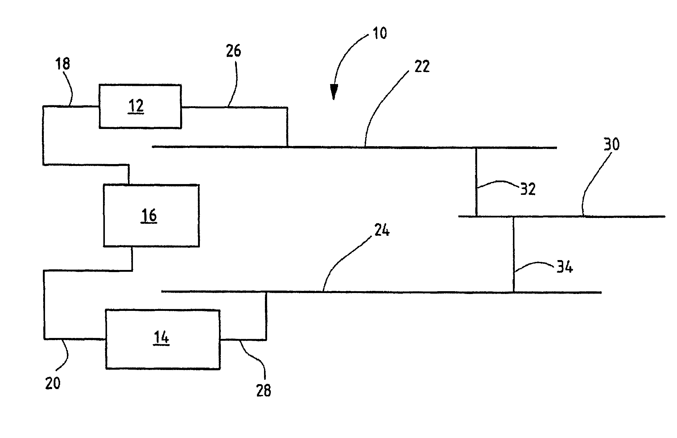
[0044]FIG. 1 shows a drive system 10 according to the invention.

[0045]The drive system 10 comprises a first drive module 12 and a second drive module 14, which can be controlled by the controller 16 via the lines 18, 20. The two drive modules 12, 14 can be controlled by a controller 16 independently of each other and can continuously output power set by the controller 16. The drive system 10 comprises a first branch 22 and a second branch 24, wherein the two branches in FIG. 1 are shown merely schematically in the form of a shaft.

[0046]The drive module 12 can be connected to the first branch 22 via the schematically shown gear connection 26. The drive module 14 can be connected to the second branch 24 via the schematically shown gear connection 28. Preferably, the gear connections 26, 28 are always connected; for example, an output shaft of the drive modules 12, 14 is locked in rotation via a corresponding gear connection 26, 28 to the first and to the second branch 22, 24, respecti...

second embodiment

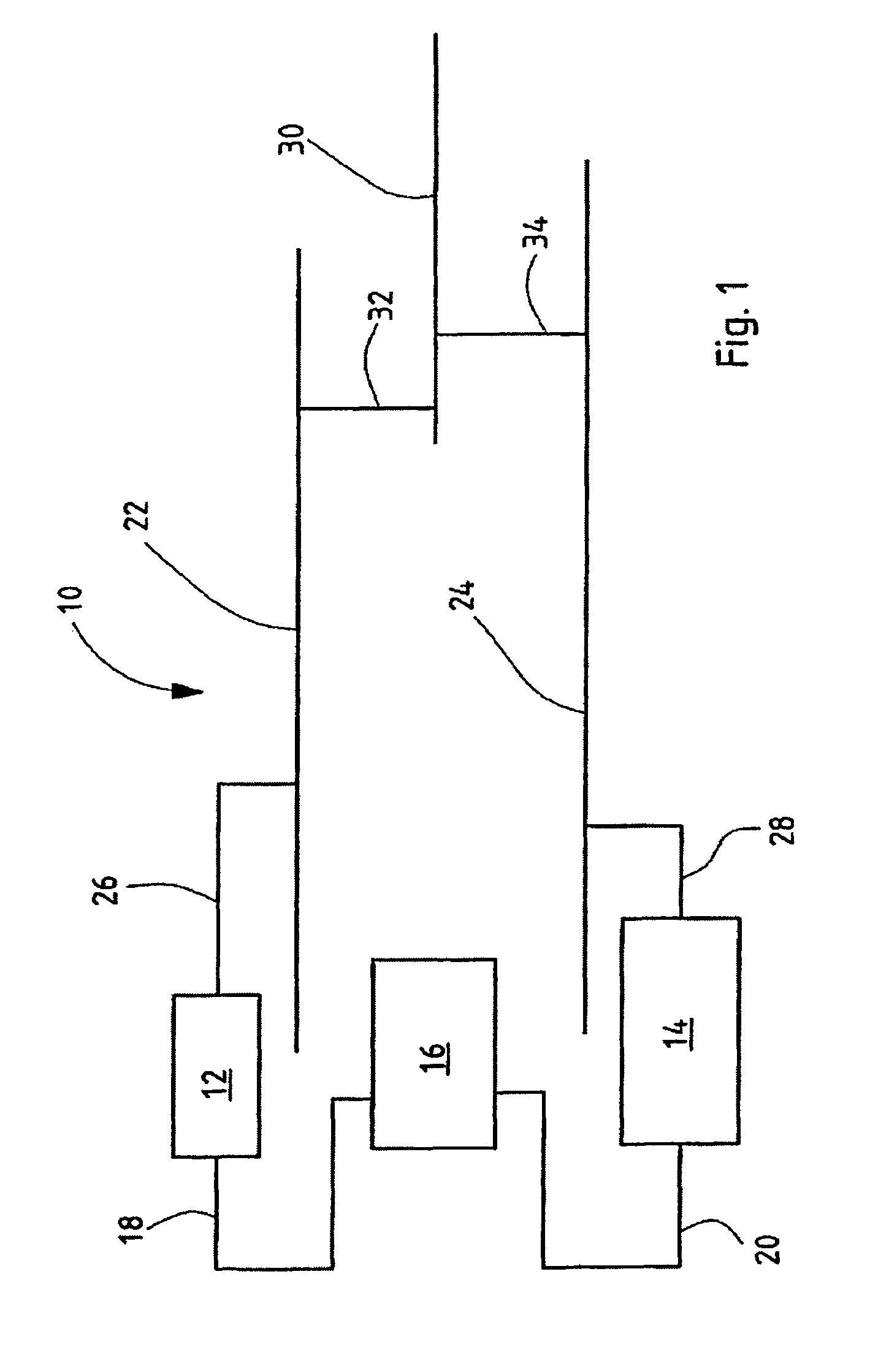
[0052]FIG. 2 also shows in a schematic view a drive system 10 according to the invention. In terms of the components shown in FIG. 1, the drive system 10 shown in FIG. 2 is comparably constructed. In this embodiment, an energy source 36 is provided, which can be connected at the input interface 38 (shown with dashed lines) to the drive system 10. In detail, the energy source 36 comprises a diesel engine, which is coupled to the input shaft 40 of the drive system 10. The diesel engine transmits mechanical torque to the two branches 22, 24, which is realized with the aid of the schematically shown component 42. The energy source 36 also comprises a converter module 44, which is also driven mechanically by the diesel engine or the energy source 36. The converter module 44 comprises an electric machine, which operates as a generator and which generates electric alternating current when the diesel engine is operating. The generated alternating current is first converted into direct curre...

third embodiment

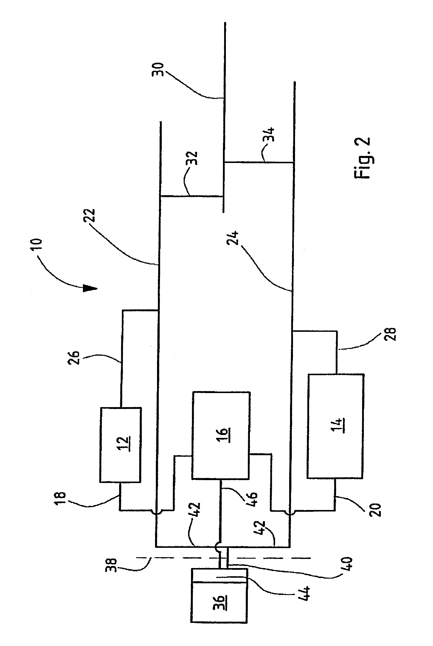
[0053]FIG. 3 shows the present invention, wherein the drive system 10 according to the invention can be connected at its input interface 38 to a energy source 36 constructed in the form of a diesel engine. In this embodiment, the energy source 36 is mechanically coupled to the second branch 24. The first branch 22 is non mechanically coupled to the energy source 36. The converter module 44, which is constructed in the form of an electric machine embodied as a generator, is always coupled to and driven with the second branch 24. The electric current generated by the converter module 44 is fed via the connection line 46 to the controller 16, which on its side can temporarily store the electric current in a buffer (not shown in FIG. 3); for example, in a capacitor or accumulator. On the one hand, the second drive module 14 can be driven via connection line 20 and, on the other hand, the first drive module 12 can be driven via connection line 18.

[0054]The first branch 22 can be driven o...


PUM


Abstract

A drive system for a vehicle is provided, in particular for an agricultural or industrial utility vehicle. The drive system comprises a first and a second drive assembly (, a first and a second branch, at least one control unit and at least one output interface. The first drive assembly is connectable to the first branch. The second drive assembly is connectable to the second branch. The first branch and/or the second branch is/are reversibly connectable to the output interface. The drive assemblies are controllable by the at least one control unit such that the drive assemblies output independently from each other infinitely variable power.

Description

FIELD OF THE INVENTION[0001]The invention relates to a drive system for a vehicle, particularly for an agricultural or industrial utility vehicle. The present invention further relates to a vehicle with such a drive system, as well as to a drive module and / or a converter module and / or a controller for such a drive system.BACKGROUND OF THE INVENTION[0002]Electric motors are increasingly being used to drive vehicles, which draw their energy from internal combustion engine driven generators, batteries, or fuel cells. To achieve a higher spread, in many cases shiftable gear stages are arranged after the electric motors, but usually the power transfer is realized without shifting stages. The term “spread” is understood to be the speed range over which nominal power can be reached at the power take off.[0003]For road and rail vehicles, the state-of-the-art procedure currently described usually has been sufficient for achieving the desired driving power. Here, the spread lies on the order ...

Claims


Application Information

Patent Timeline
Patent Type & Authority Patents(United States)
IPC IPC(8): G06F17/00B60L9/00B60K6/48G05D1/00B60L11/00G05D3/00G06F7/00
CPCY02T10/6221B60K6/48B60L2200/26B60L15/20B60L2200/40Y02P90/60Y02T10/62Y02T10/64Y02T10/72
Inventor TARASINSKI, NICOLAIGUGEI, RAINER
Owner DEERE & CO
Why Eureka
Try Eureka