Assembled shaft element, particularly assembled camshaft for valve-controlled internal combustion engines

a technology of internal combustion engine and camshaft, which is applied in the direction of machines/engines, valve drives, couplings, etc., can solve the problems of reducing the transmittable torque, affecting the formfit and/or force fit between the shaft and the hub body, and significant noise emissions during engine operation. , to achieve the effect of simple assembly, reliable avoiding unwanted noise emission, and simple structur

Active Publication Date: 2014-03-04
AUDI AG
View PDF14 Cites 14 Cited by
  • Summary
  • Abstract
  • Description
  • Claims
  • Application Information

AI Technical Summary

Benefits of technology

[0006]It is therefore an object of the invention to propose an assembled shaft element, in particular an assembled camshaft, which is simple in structure and yet reliably avoids an unwanted noise emission during operation of the shaft. Further, it is an object to provide a method with which a technically simple production of an assembled shaft is possible.
[0009]Besides the fact that such an arrangement according to the invention eliminates the need for axial securement of the hub body on the shaft, alternate torques occurring during shaft operation are, particularly advantageously, supported very well and absorbed by the tooth system so that unwanted sound emissions are eliminated or reduced significantly.
[0010]Especially advantageous and favorable with regard to manufacture, the interference fit can be realized by increasing the tip circle diameter of the shaft splines relative to a nominal dimension and / or decreasing the root circle diameter of the hub body splines relative to this nominal dimension. As a result, the tooth tips of the splines on the shaft and the tooth roots of the splines on the hub body in opposite relationship without contacting each other are configured such that their cooperation results in the mentioned interference fit. The alterations on the splines and the additional effort with regard to manufacturing can be realized in a most simple manner and with little effort.
[0011]In particular, the splines can be implemented on the shaft and on the hub body by grounding the tip circle diameter to fit and to broach the root circle diameter to fit. Preferably, the splines with interference fit are hereby manufactured to a press fit in a transition-fit near region, in particular manufactured with a smaller overlap (preferably to H7 / r6 or H7 / s6 or H7 / u6) than a shaft-hub-connection which is configured without splined tooth system, for example one which is connected by a material-removing process and transmits a same operating torque. The relatively small overlap ensures easy assembly and guarantees that the hub bodies which already have been prefabricated precisely to size suffer no subsequent deformation; still a sufficient support of occurring alternate torques is ensured during operation particularly during cam operation.
[0012]For especially easy assembly when joining the hub bodies in a press fit and in the longitudinal press fit, the corresponding splines on the shaft can have a slanted run-on surface to facilitate sliding onto the splines. Preferably, this sliding is carried out in combination with a suitable lubricant or separation agent, which can be water-based or oil-based to avoid seizing and thus damage to the hub body or the hub body splines during assembly, when sliding such interference-fit shaft areas or shaft sections over each other, which have identical interference fit dimension as an interference-fit shaft area which is assigned to and in sliding direction positioned behind a hub body that is to be slid on.
[0013]Alternatively, when joining in the transverse press fit, the shaft can be cooled and / or the hub body heated to the extent that the hub body can be pushed onto the shaft or splines substantially without force. These afore-described mounting aids have the additional advantage that in hub body arrangements which alternate between interference fit and sliding fit, the hub bodies that are to be joined can be pushed easily over several splines which precede the hub body in order, for example via a sliding fit according to claim 8 and here in particular in combination with interference-fit hub body connections and sliding-fit hub body connections that have substantially the same or essentially uniform toothing parameters. Uniform toothing parameters relate hereby in particular to approximately same dimensions and arrangements of the respective spline areas.

Problems solved by technology

Since for example such a splined tooth system has play, significant noise emissions can occur during engine operation.
These noise emissions are caused in particular by the alternating torque which acts on the splined tooth system and is caused for example by valve and pump cams.
Such a connection however, has the disadvantage that the chip formation decreases the transmittable torque, because material is broken out of the joining gap and can therefore no longer contribute to the formfit or the tension build up and thus to the force fit.
This shaping however poses the risk of formation of cavities and thus tension losses which in turn can adversely affect the formfit and / or force fit between the shaft and the hub body.

Method used


Image

  • Assembled shaft element, particularly assembled camshaft for valve-controlled internal combustion engines
  • Assembled shaft element, particularly assembled camshaft for valve-controlled internal combustion engines
  • Assembled shaft element, particularly assembled camshaft for valve-controlled internal combustion engines

Examples


Embodiment Construction

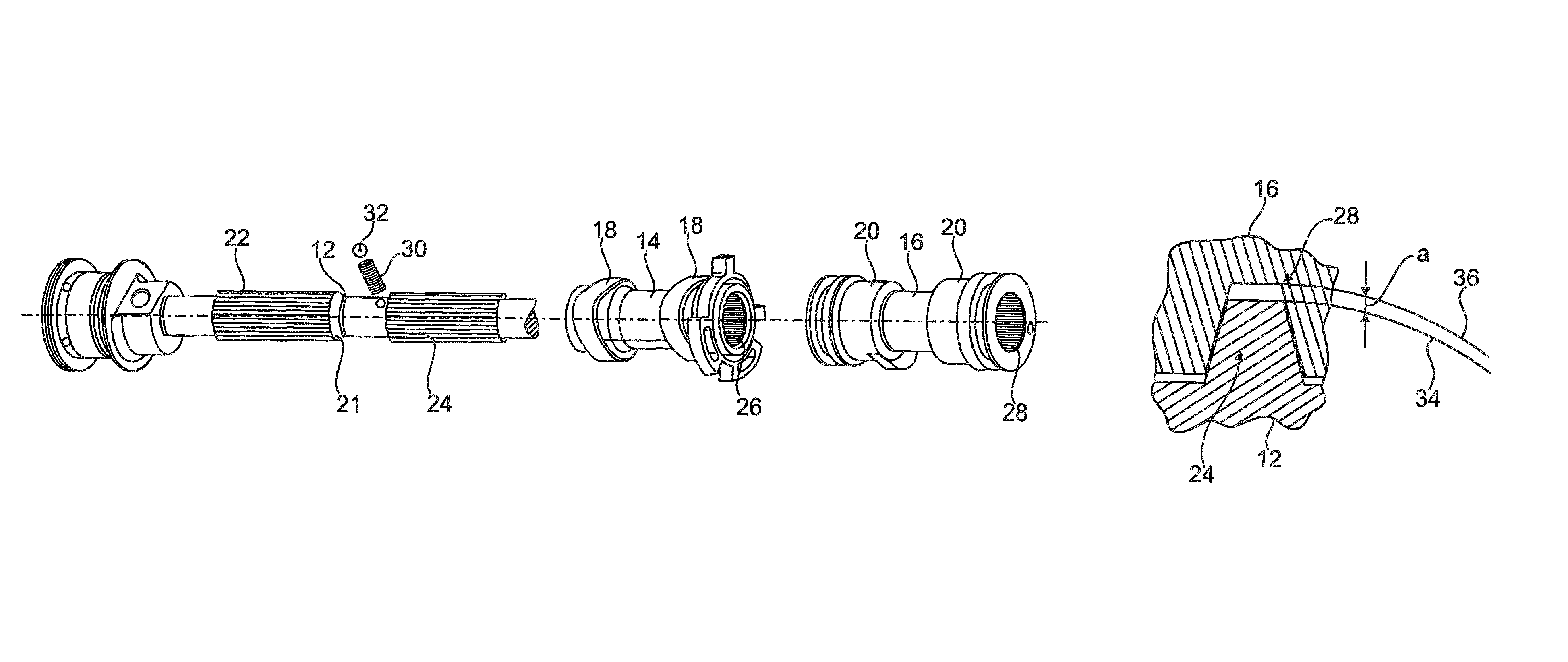
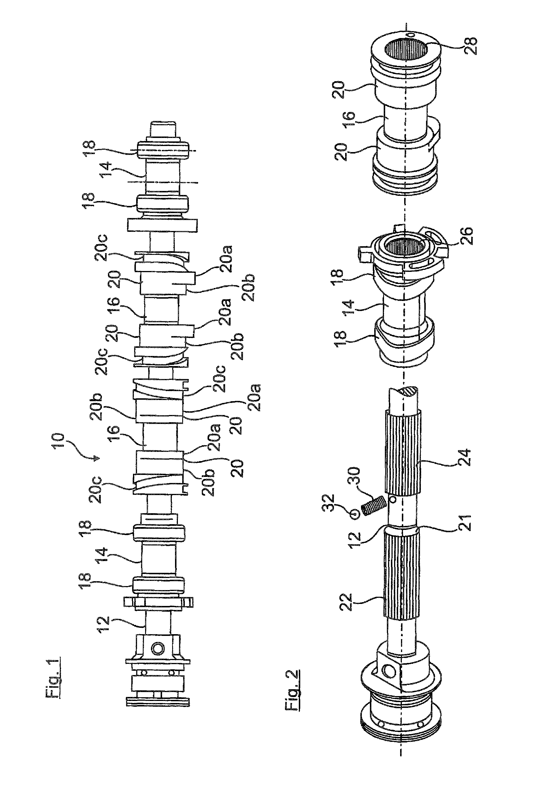
[0020]FIG. 1 shows a camshaft 10 for an internal combustion engine with partial cylinder shut down which substantially includes an inner shaft 12 which can be driven by a drive gear (for example chain wheel, not shown) and on which i.a. four cam pairs 18, 20 are arranged which are formed on hub bodies 14, 16. The camshaft 10 is described only to the extent necessary for the understanding of the present invention.

[0021]The cam pairs 18 on the hub bodies 14 are simple fixed cams, each operating a poppet valve of the valve train of the internal combustion engine.

[0022]The middle cam pairs 20 are switch cams which are fixed on the hub bodies 16 and respectively have a cam contour 20a and a circular symmetrical contour 20b matching the cam base circle. Further, sliding guides 20c are assigned adjacent to the cam pairs 20 for allowing the cam pairs 20 with the hub bodies 16 to move axially. A switch pin which is not shown engages hereby alternatingly into one or the other sliding guide 20...


PUM

PropertyMeasurementUnit
diameteraaaaaaaaaa
operating torqueaaaaaaaaaa
dimensionaaaaaaaaaa

Abstract

The present invention relates to an assembled shaft element, in particular an assembled camshaft for valve-controlled internal combustion engines, wherein a hub body having at least one functional part, in particular at least one cam, is held on a shaft by a formfit connection using a splined tooth system in the circumferential direction, wherein the splined tooth system includes shaft splines formed on the shaft and interacting with hub body splines formed in a hub body recess. According to the invention, the at least one hub body (14) is held in addition to the circumferential formfit connection by an interference fit on the shaft (12) implemented by a press fit between a tooth circle of the shaft splines (22) and a root circle of the hub body splines (26). The invention further relates to a method for producing an assembled camshaft for valve-controlled internal combustion engines.

Description

CROSS-REFERENCES TO RELATED APPLICATIONS[0001]This application is the U.S. National Stage of International Application No. PCT / EP2010 / 003412, filed Jun. 8, 2010, which designated the United States and has been published as International Publication No. WO 2010 / 142408 and which claims the priority of German Patent Application, Serial No. 10 2009 024 455.7, filed Jun. 10, 2009, pursuant to 35 U.S.C. 119(a)-(d).BACKGROUND OF THE INVENTION[0002]The invention relates to an assembled shaft element, in particular an assembled camshaft for valve-controlled internal combustion engines, and to a method for making an assembled shaft element.[0003]For internal combustion engines with variable valve control and / or shut down of individual cylinders, structures are known having cams or cam pairs that are axially movable on the shaft and which, for example, carry two different cam contours per poppet valve and thus cause different control times when being switched. If one of the contours has a circ...

Claims


Application Information

Patent Timeline
Patent Type & Authority Patents(United States)
IPC IPC(8): F01L1/04
CPCF16D2001/103F01L2013/0052B21D53/845F01L13/0042F01L2820/01F01L2001/0473F01L2103/00F01L1/047F16D1/101F01L2810/04F01L2303/00Y10T29/49945Y10T74/2101Y10T29/49293Y10T29/49
Inventor DOLLINGER, PETERSCHIMMER, THOMAS
Owner AUDI AG
Why Eureka
Try Eureka