Ultrasound guided robot for flexible needle steering

a flexible needle and ultrasound technology, applied in the direction of sensors, catheters, diagnostics, etc., can solve the problems of difficult to see the needle shaft, difficult to interpret such ultrasound images, and difficulty in resolving needles, etc., to achieve the effect of less radiation hazards, less radiation hazards, and less general availability

Active Publication Date: 2014-03-04
TECHNION RES & DEV FOUND LTD
View PDF18 Cites 56 Cited by
  • Summary
  • Abstract
  • Description
  • Claims
  • Application Information

AI Technical Summary

Benefits of technology

[0017]This disclosure describes a system and method for steering a flexible needle in a soft tissue under the real time guidance of ultrasound imaging. The use of ultrasound provides advantages over other imaging modalities. The main advantages over the use of X-ray imaging are the absence of radiation hazard, more general availability and lower cost.
[0029](iv) a control system to minimize differences between the ascertained position of the tip of the needle and the desired position of the tip according to the predetermined trajectory,
[0039](iv) a control system controlling the motion of the robot motion to minimize differences between the ascertained position of the tip of the needle and the desired position of the tip according to the predetermined trajectory,wherein the control system may be adapted to utilize a model of the needle as a flexible beam having a plurality of virtual springs connected laterally thereto to simulate lateral forces exerted by the tissue on the needle, and wherein the lateral forces exerted by the tissue on the needle may be determined from elastic properties of the tissue derived from the tissue displacement pattern around the needle tip.
[0063](iv) a control system to minimize differences between the ascertained position of the tip of the needle and the desired position of the tip according to the predetermined trajectory,
[0073](iv) a control system controlling the motion of the robot motion to minimize differences between the ascertained position of the tip of the needle and the desired position of the tip according to the predetermined trajectory,

Problems solved by technology

However, the interpretation of such an ultrasound image may not be straightforward because of limitations in the visibility of the needle in such imaging.
If the ultrasound imaging were to be performed in directions generally sideways to the needle, as is done with X-ray fluoroscopy, (though with ultrasound imaging, this would not usually be a practical method of operation) at least part of the projection of the needle shaft could be seen but the needle tip may not be clearly visible.
On the other hand, at imaging directions close to the angle of needle insertion, which are the directions generally used for ultrasound imaging, the needle tip is clearly visible as a bright region, which moves as the needle advances, but the needle itself, is generally difficult to resolve.
Thus, the use of US imaging in the commonly used configuration, which enables the position of the tip of the needle to be tracked, this being the ultimate object of the system, does not enable the shaft of the needle to be readily seen.
Without knowledge of the stiffness coefficients at each insertion increment of the needle, the inverse kinematics equation cannot be solved.
At best, an approximate value of the stiffness could be used for the entire insertion, but since the stiffness of the tissue may vary along the needle trajectory, the accuracy of such a procedure would be poor.

Method used


Image

  • Ultrasound guided robot for flexible needle steering
  • Ultrasound guided robot for flexible needle steering
  • Ultrasound guided robot for flexible needle steering

Examples


Embodiment Construction

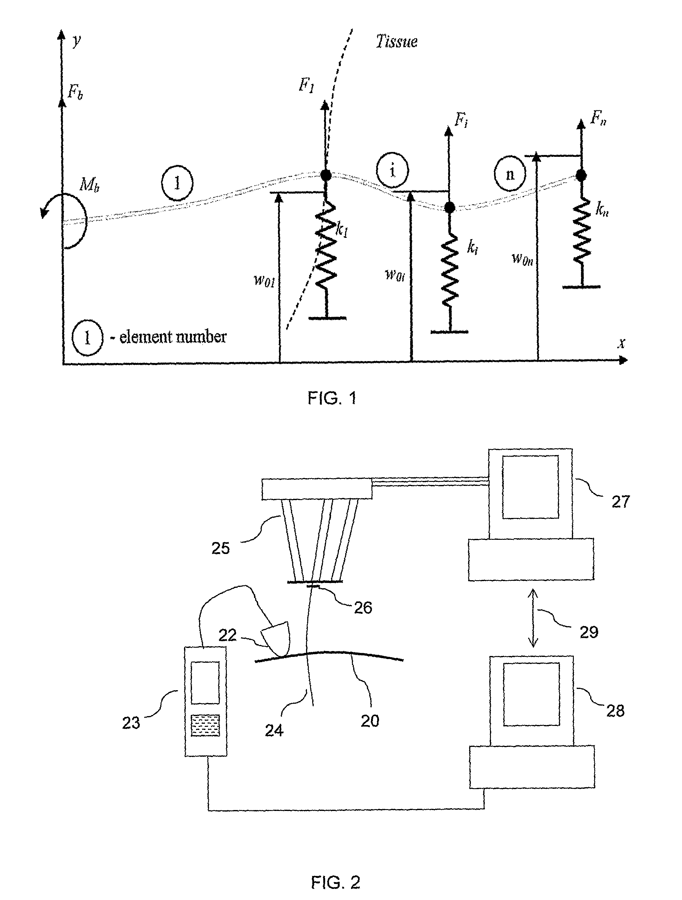
[0086]Reference is now made to FIG. 2, which is a schematic illustration of an exemplary system for performing the controlled needle insertion methods described in this application. The flexible needle 24 is shown held in the insertion robot 25 and the insertion progress into the subject's tissue 20 is shown being monitored by an ultrasound (US) imaging system, including the ultrasound probe 22 and its control and display system 23. The probe may generally incorporate both the ultrasound transducer and the sensor system for the US energy returned from the needle and tissue. The US control system 23 may generally include the US power supply and the signal processing routines for analyzing the signals received and for generating the US image therefrom.

[0087]The robot 25 used for holding the needle 24, and for aligning and propelling it into the patient's tissue 20 may be an RSPR 6DOF parallel robot, such as that described in the article entitled “Image-guided Robot for Flexible Needle...


PUM


Abstract

A robotic system for flexible needle steering under ultrasound imaging. A robot is used to steer the needle along a predetermined curved trajectory by maneuvering the needle base. The needle tip position is detected by an ultrasound sensor and the tracking error of the needle tip from a predetermined needle path is input to a controller which solves the inverse kinematic based on the needle position, and the needle and tissue properties. The control algorithm uses a novel method to detect the elastic properties of the tissue by analyzing tissue motion at the region in front of the needle tip. The inverse kinematic solution may be performed on a model of the needle as a flexible beam having laterally connected virtual springs to simulate lateral forces exerted by the tissue elasticity. The system is able to direct the needle to a target within the tissue while circumventing forbidden regions.

Description

[0001]This is a 35 U.S.C. §371 application of PCT / IL2009 / 000537, filed May 31, 2009, and claims the benefit under 35 U.S.C. §120 of said PCT application, and further claims the benefit under 35 U.S.C. §119(e) of U.S. Provisional Patent Application USSN 61 / 071,954, filed May 28,2008. The contents of these priority applications are incorporated herein by reference.FIELD OF THE INVENTION[0002]The present invention relates to the field of the control of the insertion of flexible needles into a tissue, and especially when the insertion of the needle is observed by ultrasound imaging.BACKGROUND OF THE INVENTION[0003]Numerous clinical procedures involve needle insertion for diagnostic and therapeutic purposes. Such procedures include biopsies, regional anesthesia, drug delivery, blood sampling, prostate brachytherapy and ablation. These procedures require navigation and accurate placement of the needle tip at an organ, vessel or a lesion. The validity of a diagnosis or the success of a the...

Claims


Application Information

Patent Timeline
Patent Type & Authority Patents(United States)
IPC IPC(8): A61B5/103
CPCA61B2019/5276A61B19/5244A61B2019/5265A61B8/485A61B90/11A61B17/3403A61B34/20A61B34/30A61B2017/3409A61B2017/3413A61B2034/107A61B2034/2063A61B2034/2065A61B2034/301A61B2090/378
Inventor NEUBACH, ZIPISHOHAM, MOSHE
Owner TECHNION RES & DEV FOUND LTD
Why Eureka
Try Eureka