Multiplexing solar light chamber

a solar light chamber and multi-layer technology, applied in the field of concentrating photovoltaic systems, can solve the problems that the intrinsic photovoltaic efficiency cannot improve indefinitely, and achieve the effect of improving the net generation of electricity, increasing the photovoltaic efficiency, and increasing the efficiency of photovoltaic energy

Inactive Publication Date: 2014-03-04
WATTERS JASON V +1
View PDF40 Cites 10 Cited by
  • Summary
  • Abstract
  • Description
  • Claims
  • Application Information

AI Technical Summary

Benefits of technology

[0017]The present device capitalizes on the fact that photovoltaic efficiency has increased rapidly in recent years. However, intrinsic photovoltaic efficiency cannot improve indefinitely and means to concentrate solar radiation onto active surfaces is one means of improving net generation of electricity from solar installations. The utility of the present apparatus is in providing a structure to reflect various optical functions related to concentration, dispersion, motion control, and incident light ray enhancement to stimulate photovoltaic panels with differing angular orientations in relation to the most direct angle of incidence of light from the sun. Thus, the present device is a light chamber wherein radiation, preferably solar radiation, is bounced around in a highly reflective and magnified manner. Photovoltaic solar arrays or panels are strategically placed within the light chamber to maximize the amount of radiation impinging upon the active surfaces.
[0018]The sun-facing plane of the device houses panels with direct light input. The orientation of the sun-facing plane may be controlled by conventional two-axis solar trackers. The system also houses photovoltaic panels opposite the sun-facing plane and placed in other angles or curves not directly facing the sun. In many implementations this allows much higher wattage output from a smaller defined geographical area than conventional concentrating photovoltaic systems. Because the present device is much smaller per watt of output, it can be used with greater acceptance in urban and suburban settings.
[0019]The primary purpose of the invention is to reduce the footprint, tracking requirements, and overall cost per delivered watt for electrical output from solar cell arrays in relation to sun exposure. A secondary benefit of the device is the creation of useable heat resulting from magnified and concentrated reflective-light. This heat can be used, for example, for residential or commercial heating purposes.

Problems solved by technology

However, intrinsic photovoltaic efficiency cannot improve indefinitely and means to concentrate solar radiation onto active surfaces is one means of improving net generation of electricity from solar installations.

Method used


Image

  • Multiplexing solar light chamber
  • Multiplexing solar light chamber
  • Multiplexing solar light chamber

Examples


Embodiment Construction

[0050]At the heart of the present device is a concentrating photovoltaic system that is compact, cost-effective, modular, efficient, and decreases the need for large-area solar array installations and multiple solar trackers. The device generates more electricity per area of active photovoltaic surface (and per overall unit area) than conventional solar arrays.

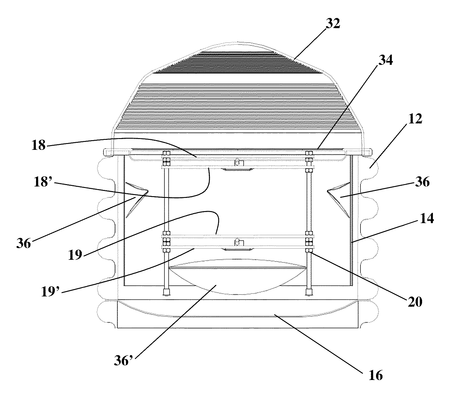
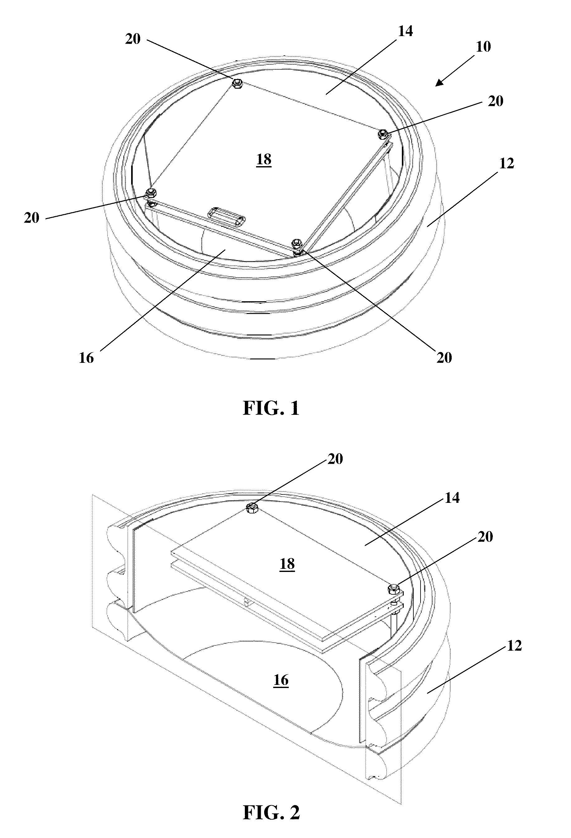
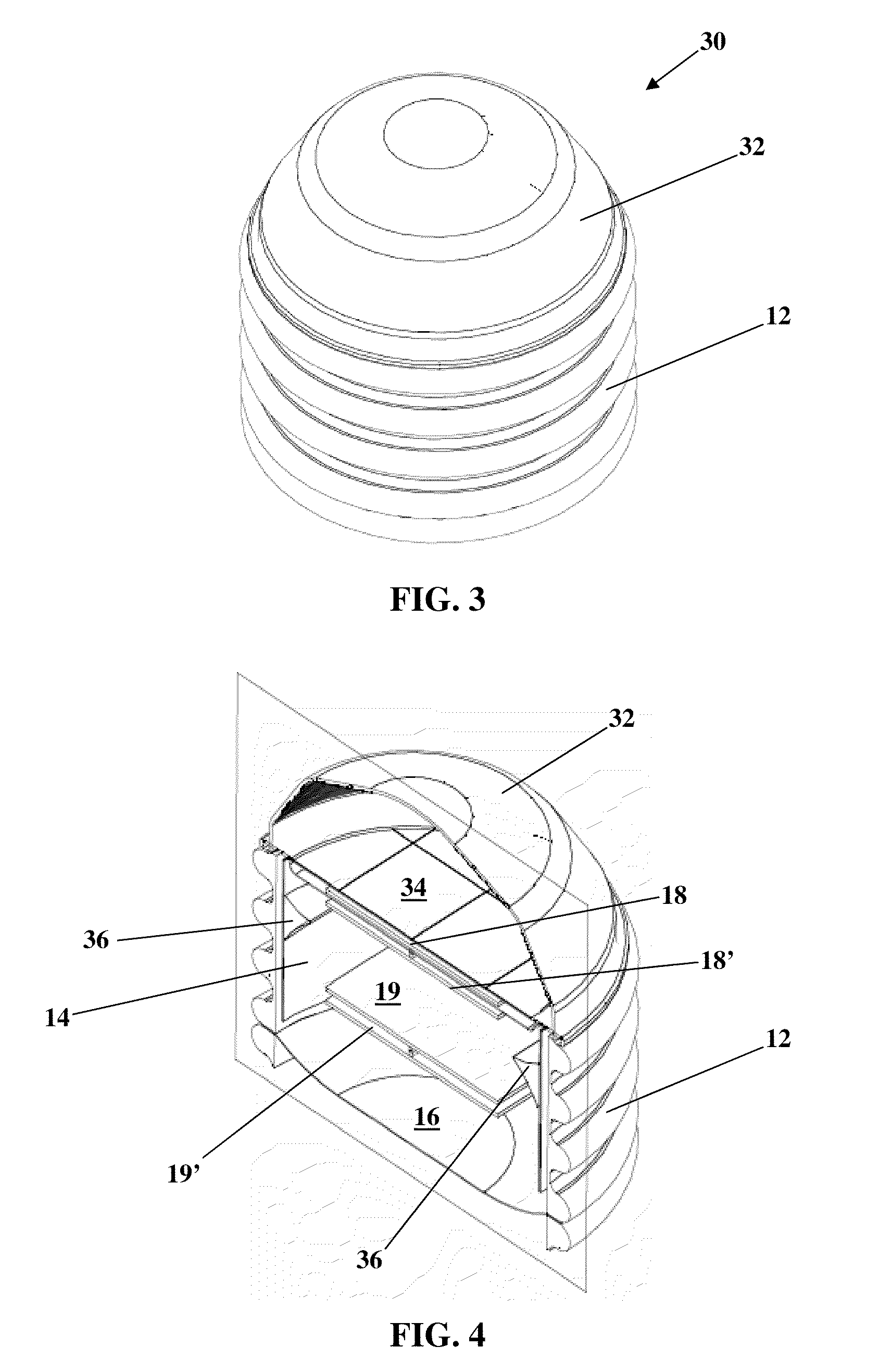
[0051]Throughout all of the drawing figures, the same reference numerals refer to the same or analogous elements of the device. Referring now to FIGS. 1 and 2, these two figures illustrate a first version 10 of the invention. FIG. 1 is a perspective view of the first version of the device, and FIG. 2 is a vertical cross-sectional view of the rendering shown in FIG. 1. A cylindrical housing or case 12 having inner and outer surfaces and top and bottom faces encloses at least one solar panel 18. A circumferential sidewall reflector 14 is disposed on or proximate to the inner surface of the housing. Preferably, the sidewall refle...


PUM


Abstract

Described is a light chamber for amplifying solar radiation for purposes of generating electricity using photovoltaic panels. The light chamber includes a housing; a photovoltaic panel disposed within the housing; a plurality of wedge-shaped reflectors disposed within the housing configured to rotate along one or two axes and can be directed by an integrated circuit controller; a dome lens affixed to the upper end of the housing; a fresnel lens disposed between the dome lens and the photovoltaic panel; a reflector disposed around the inner surface of the housing; and another reflector disposed at or near the lower end of the housing.

Description

CROSS-REFERENCE TO RELATED APPLICATIONS[0001]Priority is hereby claimed to provisional application Ser. No. 61 / 104,951, filed Oct. 13, 2008, which is incorporated herein by reference.FIELD OF THE INVENTION[0002]The present invention generally relates to a device for collecting and concentrating light for its conversion to electricity and heat. The invention is more specifically directed to a concentrating photovoltaic system that generates increased electrical output, while occupying a small amount of space.BACKGROUND OF THE INVENTION[0003]The photovoltaic effect was first described in 1839 by French physicist A. E. Becquerel. However, it was not until after World War II that Russell S. Ohl invented and patented the modern junction semiconductor solar cell (in 1946). See U.S. Pat. No. 2,402,662. It was not until the mid-1970's that practical and effective gallium-arsenide (GaAs) solar cells became commercially available.[0004]In the decades since, the science and technology related ...

Claims


Application Information

Patent Timeline
Patent Type & Authority Patents(United States)
IPC IPC(8): H01L31/052H01L31/048G02B17/00
CPCH01L31/0525Y02E10/52H01L31/0232H01L31/0524H01L31/0522H01L31/0547H01L31/0543H01L31/054
Inventor WATTERS, GEORGE, M.
Owner WATTERS JASON V
Why Eureka
Try Eureka