Wet electrolytic capacitor and method for fabricating of improved electrolytic capacitor cathode

a technology of electrolytic capacitors and wet electrolytic capacitors, which is applied in the direction of electrolytic capacitors, capacitors, transportation and packaging, etc., can solve the problems of increased manufacturing costs, limited packaging of capacitors, and serious drawbacks of powders and flakes used in capacitors

Active Publication Date: 2014-03-18
COMPOSITE MATERIALS TECH
View PDF5 Cites 17 Cited by
  • Summary
  • Abstract
  • Description
  • Claims
  • Application Information

AI Technical Summary

Benefits of technology

[0023]I have now found that the process described in my aforesaid parent application advantageously may be used to form cathodes for wet tantalum capacitor systems by cutting conventional valve metal filaments or wires in a ductile metal matrix into short segments, leaching out the ductile metal so as to leave the short valve metal filaments intact, and forming or casting the valve metal filaments into a thin sheet from a slurry. In a preferred embodiment of my invention, the valve metal comprises tantalum while the ductile metal comprises copper, and the tantalum fibers are cast in the form of a thin sheet from an aqueous slurry using a continuous Doctor Blade casting method.

Problems solved by technology

In practice, however, there are packaging restrictions on the capacitor.
As discussed below, the use of such powders and flakes can have serious drawbacks.
Aspecting tantalum particles by ball milling and other processes aimed at improving powder performance, while effective, has practical drawbacks, including increased manufacturing costs and a marked decrease in product yield.
The very fine tantalum powders commercially available today have several serious problems with respect to anode and cathode fabrication.
One significant problem in particular is a sensitivity to surface area loss during sintering.
Unfortunately, the fine particles of high capacitance powders and flakes lose surface area at temperatures over 1500° C. A loss of surface area results in lower capacitance, reducing the benefit of using the higher specific capacitance powder.
As the forming voltage increases, more of the tantalum is consumed, resulting in a loss of capacitance.
As the powder becomes finer, this problem becomes increasingly serious.
Another drawback to fine powders is “tortuousity”, which can lead to poor electrolyte fill factor.
Eventually, it becomes extremely difficult, if not impossible, to completely infiltrate the compact.
A final difficulty in using high specific capacitance tantalum powders is their poor flowability.
Flakes and highly aspected powders tend not to flow uniformly, which can lead to large variability in production runs.
Although fine tantalum powders and flakes are subject to the problems briefly discussed above, the problem of sensitivity to anodization conditions comes into play primarily for anode fabrication.
However, at reduced sizes, the copper cannot readily be leached out due to the presence of the continuous tantalum layers.

Method used


Image

  • Wet electrolytic capacitor and method for fabricating of improved electrolytic capacitor cathode
  • Wet electrolytic capacitor and method for fabricating of improved electrolytic capacitor cathode
  • Wet electrolytic capacitor and method for fabricating of improved electrolytic capacitor cathode

Examples


Embodiment Construction

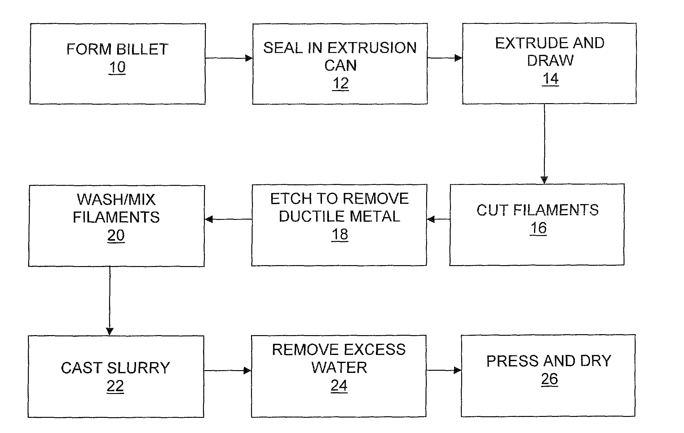
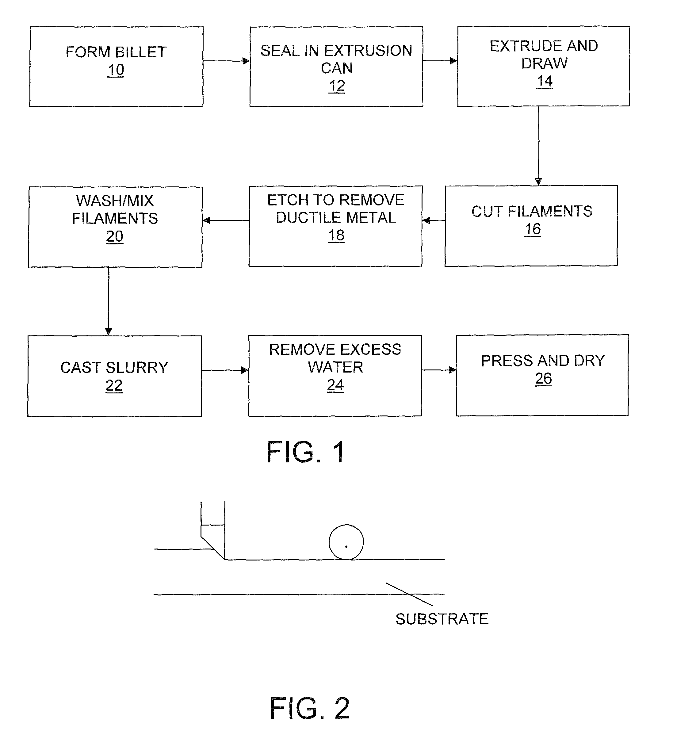
[0028]Referring to FIGS. 1 and 2, the process starts with the fabrication of valve metal filaments, preferably tantalum, by combining filaments or wires of tantalum with a ductile material, such as copper to form a billet at step 10. The billet is then sealed in an extrusion can in step 12, and extruded and drawn in step 14 following the teachings of my '196 U.S. patent. The extruded and drawn filaments are then cut or chopped into short segments, typically 1 / 16th-¼th inch long at a chopping station 16. Preferably the cut filaments all have approximately the same length. Actually, the more uniform the filament, the better. The chopped filaments are then passed to an etching station 18 where the ductile metal is leached away using a suitable acid. For example, where copper is the ductile metal, the etchant may comprise nitric acid.

[0029]Etching in acid removes the copper from between the tantalum filaments. After etching, one is left with a plurality of short filaments of tantalum. T...


PUM

PropertyMeasurementUnit
temperatureaaaaaaaaaa
temperaturesaaaaaaaaaa
voltagesaaaaaaaaaa

Abstract

A process for making a valve metal material useful for forming electrolytic devices comprising the steps of: establishing multiple tantalum or niobium components in a billet of a ductile material; working the billet to a series of reduction steps to form said tantalum or niobium components into elongated elements; cutting the resulting elongated elements and leaching the ductile metal from the elements; washing and mixing the cut elements; and forming the cut elements into a sheet. The resulting sheet may be formed into anodes and cathodes and assembled to form a wet electrolytic capacitor.

Description

CROSS REFERENCE TO RELATED APPLICATION[0001]This application is a CIP of the yet to be filed National Phase of PCT / US08 / 86460 filed Dec. 11, 2008, the contents of which are incorporated herein by reference. This application also claims priority from U.S. Provisional Application Ser. No. 61 / 218,885, filed Jun. 19, 2009.BACKGROUND OF THE INVENTION[0002]In my aforesaid parent application, I describe production of tantalum and niobium-based materials useful as electrolytic capacitor anodes. As described in my aforesaid parent application, tantalum-based electrolytic capacitors have found increasing use in microelectronics. The combination of small package size, insensitivity to operating temperature, and excellent reliability have made them the choice over ceramic multilayer and aluminum foil-based capacitors for many applications. As the state of the art in microelectronics continues to progress, demand has grown for more efficient tantalum electrolytic capacitors.[0003]An electrolytic...

Claims


Application Information

Patent Timeline
Patent Type & Authority Patents(United States)
IPC IPC(8): H01G9/00
CPCH01G9/0525B22F3/002B22F3/20B22F2998/10B22F3/12B22F9/04B22F1/004C23F1/00B22F3/18Y10T29/417B22F1/062
Inventor WONG, JAMES
Owner COMPOSITE MATERIALS TECH
Why Eureka
Try Eureka