Drive device for alternating current motor and electric motor vehicle

a technology of alternating current motor and electric motor, which is applied in the direction of motor control for motor oscillation damping, electric energy management, and conversion with intermediate conversion to dc, can solve the problems of increasing the amount of attachment and adjustment work, increasing the cost, and the like due to the essential information sensor, so as to reduce the generation the effect of minimizing the harmonic wave and reducing the amount of electromagnetic noise and loss

Active Publication Date: 2014-03-18
HITACHI LTD
View PDF19 Cites 17 Cited by
  • Summary
  • Abstract
  • Description
  • Claims
  • Application Information

AI Technical Summary

Benefits of technology

[0025]For the purpose of estimating and calculating a magnetic flux inside of the alternating current motor, a harmonic voltage is not applied intentionally, and hence the output waveform of the inverter becomes an ideal pulse width modulation waveform. As a result, electromagnetic noise and loss caused by the harmonic wave are minimized. In particular, in a high-capacity alternating current motor, an absolute value of a harmonic current is large, and hence generation amounts of the electromagnetic noise and the loss are dramatically reduced. Further, a mathematical expression model and a data table are prepared in advance for an excessive inductance of the alternating current motor, which makes it possible to drive, without any problem, even an electric motor including a magnetic circuit which changes in a nonlinear manner.

Problems solved by technology

In the vector control, speed (or position) information of the rotor is essential, and on the other hand, there arise problems of a reduction in reliability, an increase in the amount of work for attachment and adjustment, an increase in costs, and the like due to sensors for the essential information.
According to the sensorless control technology, stable driving can be achieved by a method based on an induced voltage of the electric motor in a region in which the rotational speed is high, whereas it is extremely difficult to realize the vector control in a region close to zero speed in which the induced voltage becomes smaller.
Returning to the principle of the vector control of the alternating current motor, the application of a harmonic voltage is not required originally, and rather, a large number of disadvantages occur as the drive device for the electric motor.
The application of a harmonic wave as described above causes various problems.
For example, electromagnetic noise from the electric motor increases.
In order to increase the estimation sensitivity for the magnetic flux of the electric motor, it is necessary to reduce the frequency of the harmonic voltage or increase the amplitude thereof, and both cases lead to the increase in noise within an audible range (several 100 Hz to several kHz).
In addition, a large amount of harmonic components is generated in a drive current for the electric motor, so that loss (mainly, iron loss) caused by the harmonic wave considerably increases.
The increase in loss leads directly to a problem of heat generation, and thus becomes an extremely important factor in terms of the design of a motor drive system.
However, if the harmonic wave is applied intentionally, the applied components themselves directly become a harmonic current to be largely generated, so that a loss larger than expected occurs.
In addition, an external circuit for detecting the current ripples is essential, and this is not practical in consideration of ringing caused by switching of the inverter and the like.
However, the nonlinearity of a magnetic circuit is strong in the electric motor of recent years, and hence it is becoming difficult to treat the constant of the electric motor as a “constant”.
Therefore, it can be said that the direct use of this method is difficult.

Method used


Image

  • Drive device for alternating current motor and electric motor vehicle
  • Drive device for alternating current motor and electric motor vehicle
  • Drive device for alternating current motor and electric motor vehicle

Examples


embodiment 1

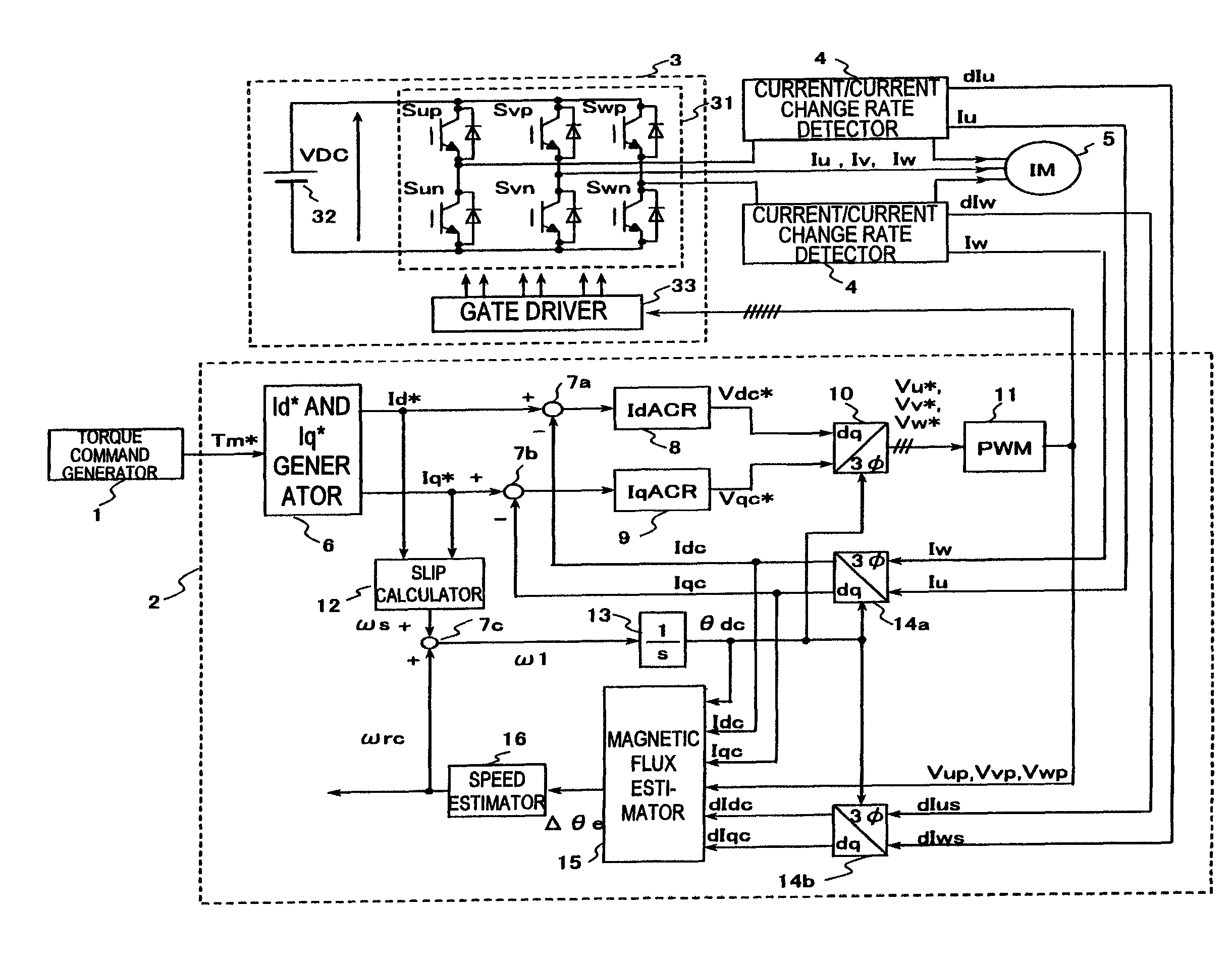
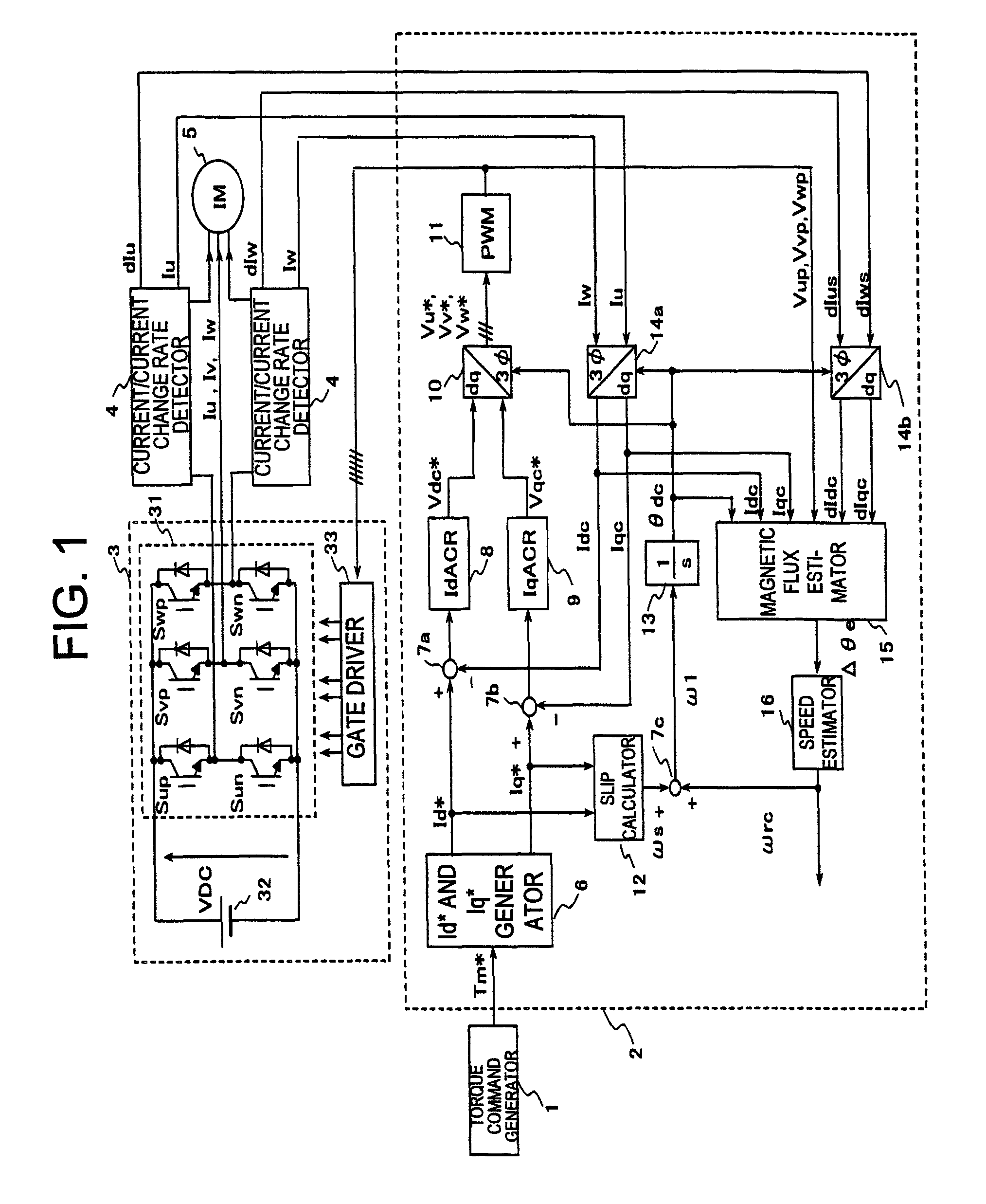
[0064]FIG. 1 is a block diagram illustrating a configuration of a drive device for an alternating current motor according to Embodiment 1 of the present invention.

[0065]This device is intended to drive a three-phase induction motor. In the rough definition, this device includes: a torque command generator 1; a controller 2; an inverter 3 including an inverter main circuit 31, an inverter power supply 32, and a gate driver 33; a current / current change rate detector 4; and a three-phase induction motor 5 (hereinafter, abbreviated as induction motor) to be driven.

[0066]The torque command generator 1 is means for issuing a generation torque command Tm* of the induction motor 5, and is a controller disposed upstream of the controller 2. A speed controller which adjusts the number of revolutions of the induction motor 5 may be provided further upstream of the torque command generator, but is omitted in the present embodiment.

[0067]The controller 2 calculates a voltage applied to the induc...

embodiment 2

[0085]Next, Embodiment 2 of the present invention is described.

[0086]In Embodiment 1, a description is given on the assumption that the controller 2 is realized by the analog circuit, and hence high-speed processing is essential to realize the controller by digital control. As a matter of course, if special gate logic is employed, it is not impossible to realize the controller by digitalization, but a circuit scale will be enormous.

[0087]In Embodiment 2, on the assumption of applying a microcomputer for industrial purposes or the like, a practical example is described with reference to FIG. 6 to FIG. 10.

[0088]FIG. 6 is a block configuration diagram illustrating a controller 2B which is a characteristic feature of Embodiment 2. Embodiment 2 is implemented by adopting the controller 2B instead of the controller 2 in FIG. 1.

[0089]In FIG. 6, the blocks denoted by part numbers 6 to 14 and 16 are identical with those denoted by the same numbers illustrated in FIG. 1. The characteristic fe...

embodiment 3

[0099]Next, Embodiment 3 of the present invention is described.

[0100]In Embodiments 1 and 2, the control target is the induction motor, and in Embodiment 3, a permanent magnet synchronous motor (hereinafter, abbreviated as PM motor) is applied. The PM motor can realize downsizing and higher efficiency compared with the induction motor, and hence application purposes thereof are expected to be expanded hereafter.

[0101]FIG. 11 is a configuration diagram according to Embodiment 3, which is illustrated on the basis of Embodiment 2 (FIG. 6). A controller 2C is substantially the same as the controller 2B in FIG. 6, and no change is made thereon except the slip calculator 12 is removed. In addition, the electric motor is replaced with a PM motor 5C.

[0102]In the PM motor, the drive frequency ω1 and the frequency ωrc of the number of revolutions are always synchronized with each other, and hence the slip frequency does not need to be added, so that the control configuration is more simplifie...


PUM


Abstract

Provided is a drive device for an alternating current motor which performs vector control on sensorless driving of the alternating current motor in an extremely low speed region without applying a harmonic voltage intentionally while maintaining an ideal PWM waveform. A current and a current change rate of the alternating current motor are detected, and a magnetic flux position inside of the alternating current motor is estimated and calculated in consideration of an output voltage of an inverter which causes this current change. The current change rate is generated on the basis of a pulse waveform of the inverter, and hence the magnetic flux position inside of the alternating current motor can be estimated and calculated without applying a harmonic wave intentionally.

Description

[0001]The present application is based on and claims priority of Japanese patent application No. 2010-040219 filed on Feb. 25, 2010, the entire contents of which are hereby incorporated by reference.BACKGROUND OF THE INVENTION[0002]1. Field of the Invention[0003]The present invention relates to a motor control technology for controlling as desired the number of revolutions or a torque of an alternating current motor, such as an induction motor and a permanent magnet synchronous motor, in an extremely low speed region close to zero speed, and more particularly, to a drive device for an alternating current motor and an electric motor vehicle using sensorless control, in which a rotational position angle and speed information of a rotor of the electric motor are not detected directly by a sensor.[0004]2. Description of the Related Art[0005]In order to control an alternating current motor in a highly responsive and accurate manner, it is necessary to manage a torque of the electric moto...

Claims


Application Information

Patent Timeline
Patent Type & Authority Patents(United States)
IPC IPC(8): H02P6/00H02P6/06H02P6/08H02P6/18H02P6/182H02P6/185H02P6/28H02P21/00H02P21/04H02P21/05H02P21/13H02P21/14H02P21/18H02P21/24H02P23/00H02P23/03H02P23/04H02P23/07H02P23/14H02P27/06H02P27/08
CPCB60L2210/20B60L15/025H02P21/005B60L15/08H02P21/04Y02T10/725Y02T10/643B60L2200/26H02P6/182H02P21/141H02P21/18Y02T10/64Y02T10/72
Inventor IWAJI, YOSHITAKAKANEKO, DAIGOYAMAMOTO, KOUKI
Owner HITACHI LTD
Why Eureka
Try Eureka