Differential transmission circuit and information processing system
a transmission circuit and information processing technology, applied in the direction of waveguides, electrical apparatus construction details, waveguide type devices, etc., can solve the problems of increasing the cost of the case structure components, the increase of the allowable unintentional electromagnetic radiation, and the small and steep increase in the intensity of unintentional electromagnetic radiation. to achieve the effect of increasing the cos
- Summary
- Abstract
- Description
- Claims
- Application Information
AI Technical Summary
Benefits of technology
Problems solved by technology
Method used
Image
Examples
first embodiment
[0055]A differential transmission line and an information processing system according to a first embodiment of the invention will be described.
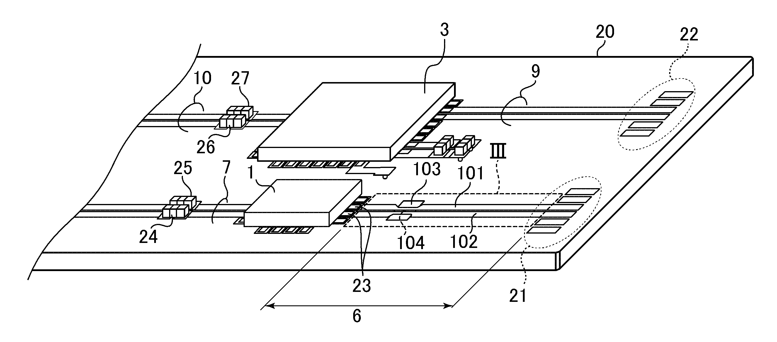
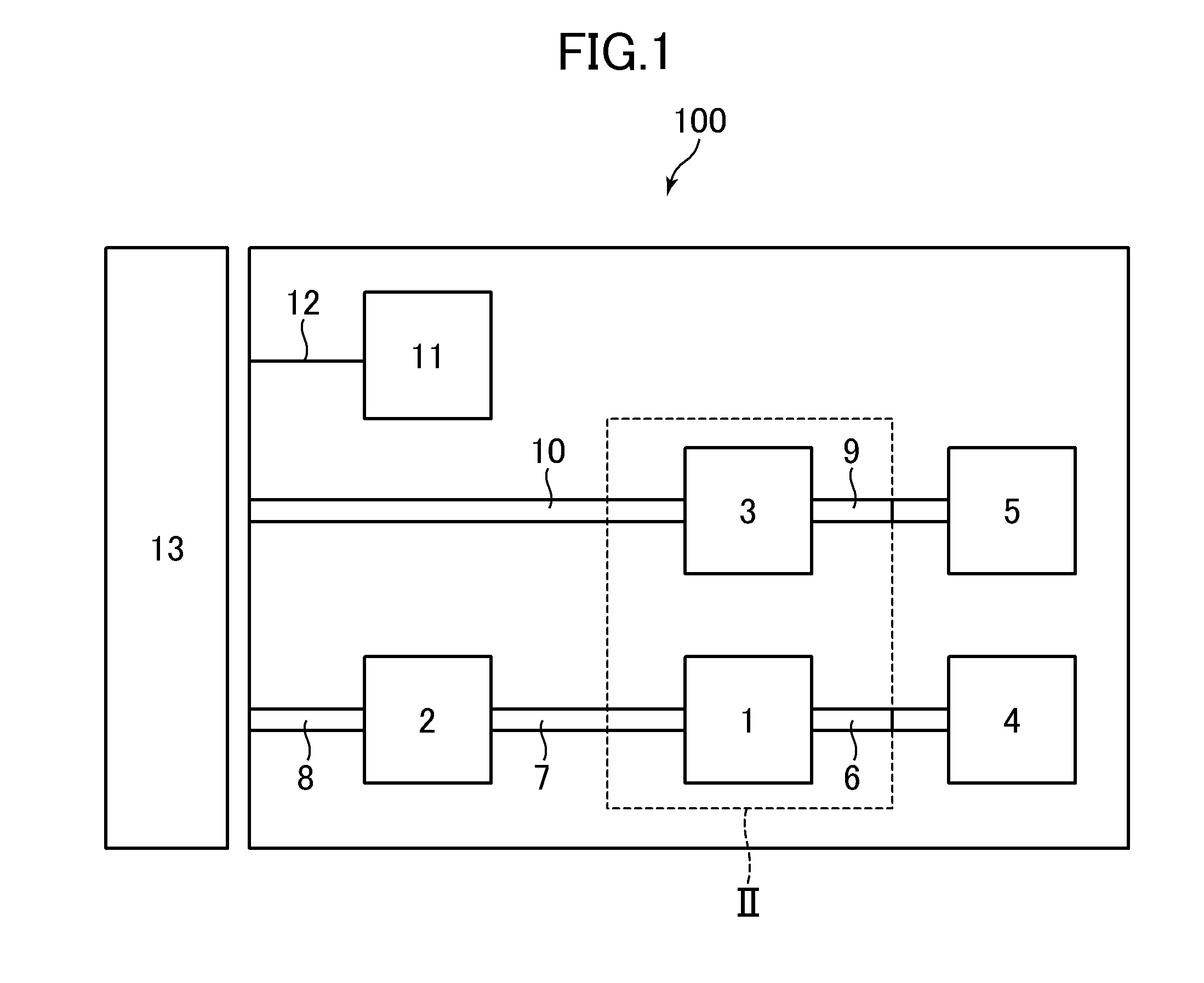
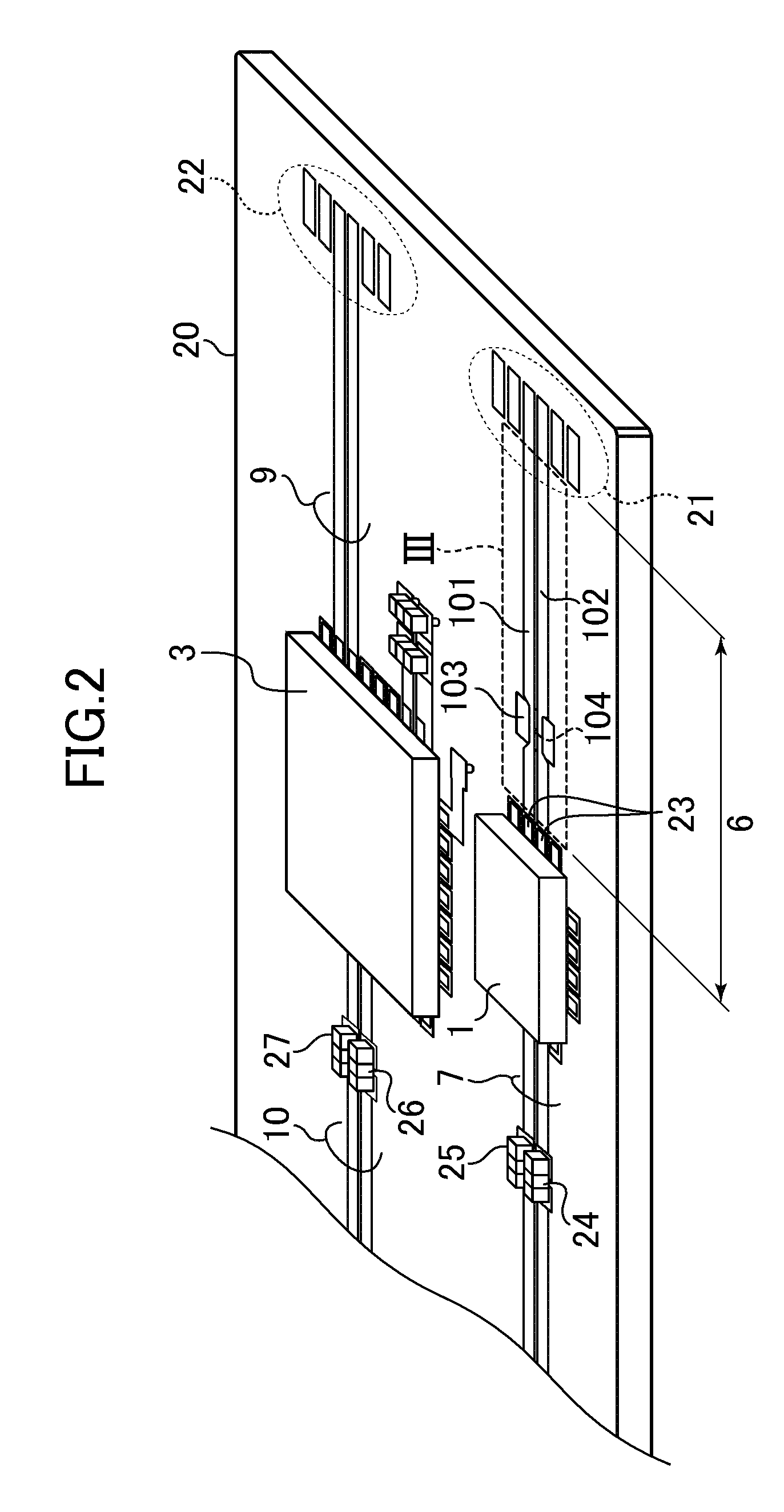
[0056]FIG. 1 is a block diagram illustrating an information processing system 100 according to the first embodiment of the invention. The information processing system 100 according to this embodiment includes a driving integrated circuit 1 (driver IC), a transmitter CDR (Clock Data Recovery) integrated circuit 2 having a CDR function, a receiver CDR integrated circuit 3, a receiver circuit 4, a transmitter circuit 5, a control unit 11, and a transmission device 13. The information processing system 100 is connected to the transmission device 13.
[0057]A transmission line is disposed between the driving integrated circuit 1 and the receiver circuit 4. Here, as described below, the transmission line includes a differential transmission line 6. A transmitter-side differential output transmission line 7 is disposed between the transmitter CDR int...
second embodiment
[0099]The basic configuration of the information processing system 100 according to a second embodiment of the invention is the same as that of the information processing system 100 according to the first embodiment. However, the configuration of the information processing system 100 according to the second embodiment is different from that of the information processing system 100 according to the first embodiment in that the desired characteristic impedance Zdiff in the differential mode of the differential transmission line 6 is 50Ω and the central frequency of the common mode band rejection filter circuit is near 10 GHz.
[0100]FIG. 10 is a top view illustrating the differential transmission line 6 according to this embodiment. As in FIG. 3, the differential transmission line 6 includes a first strip conductor 111, a second strip conductor 112, an intermediate conductive film 113, a via hole 114, and a grounded conductive layer 110. An example of the dimensions of each portion of t...
third embodiment
[0104]The basic configuration of the information processing system 100 according to a third embodiment of the invention is the same as that of the information processing system 100 according to the first embodiment. However, a differential transmission line 6 according to this embodiment is different from the differential transmission line according to the first embodiment in that the differential transmission line 6 includes two band rejection filter regions arranged in series.
[0105]FIG. 12 is a top view illustrating the differential transmission line 6 according to this embodiment. The differential transmission line 6 includes a first strip conductor 121, a second strip conductor 122, a first intermediate conductive film 123, a second intermediate conductive film 125, a first via hole 124, and a second via hole 126. Here, two band rejection filter regions are referred to as first and second band rejection filter regions, when viewed from the side (left side) of the connection pads...
PUM
 Abstract
Description
Claims
Application Information
 - R&D
- Intellectual Property
- Life Sciences
- Materials
- Tech Scout
- Unparalleled Data Quality
- Higher Quality Content
- 60% Fewer Hallucinations
Browse by: Latest US Patents, China's latest patents, Technical Efficacy Thesaurus, Application Domain, Technology Topic, Popular Technical Reports.
© 2025 PatSnap. All rights reserved.Legal|Privacy policy|Modern Slavery Act Transparency Statement|Sitemap|About US| Contact US: help@patsnap.com


