
Vehicular drive system

a technology of mechanical arrangement and vehicular drive, which is applied in the direction of electric propulsion mounting, transportation and packaging, and the etc., can solve the problems of difficult installation of electric motors, the inability of electric motors b>900/b> to be installed at the desired position on the vehicle, etc., to achieve a high degree of efficiency, reduce the degree of design limitation, and improve the effect of cooling

Active Publication Date: 2014-03-25
TOYOTA JIDOSHA KK
View PDF6 Cites 7 Cited by
  • Summary
  • Abstract
  • Description
  • Claims
  • Application Information

AI Technical Summary

Benefits of technology

[0008]The vehicular drive system described above is configured to transmit the drive force of the above-described electric motor from a selected one of the above-described one end portion and the above-described other end portion of the electric motor, making it possible to prevent an undesirable positioning of a power transmitting device such as a transmission provided to transmit the drive force of the electric motor to the drive wheels, such that the power transmitting device is disposed on one side of the above-described electric motor. Therefore, the present vehicular drive system has a reduced degree of design limitation in the position of installation of the electric motor on a vehicle. For instance, the electric motor can be disposed at a midpoint in the width direction of the vehicle, where the above-described electric motor is installed on the vehicle such that the axial direction of the above-described output rotary member is parallel to the width direction of the vehicle.
[0009]According to a second aspect of this invention, the vehicular drive system according to the first aspect of the invention is provided with (a) a differential gear device having an axis of rotation parallel to an axis of rotation of the output rotary member of the electric motor and configured to transmit the drive force of the above-described electric motor to the above-described drive wheels, and (b) the vehicular drive system is arranged such that the above-described electric motor is positioned so as to overlap with the differential gear device in a direction perpendicular to the axis of rotation of the differential gear device. According to this aspect of the invention, a large amount of an oil splashed up by a rotary motion of the differential gear device can be easily supplied to the above-described electric motor, so that the electric motor can be cooled with a high degree of efficiency. For instance, the above-described electric motor and the above-described differential gear device are accommodated together in a single housing such that the differential gear device is entirely or partially immersed in the oil within the housing.
[0010]According to a third aspect of the invention, the vehicular drive system according to the second aspect of the invention is configured such that the above-described electric motor is positioned in a vehicle on a front side of the above-described differential gear device. According to this aspect of the invention, the above-described electric motor can be cooled more effectively than the above-described differential gear device, with an air introduced into the vehicle through its front portion during forward running of the vehicle, since the vehicle runs more frequently in the forward direction than in the backward direction. Consequently, the efficiency of cooling of the above-described electric motor can be made higher than in the case where the electric motor is positioned in the vehicle on the rear side of the above-described differential gear device.
[0011]According to a fourth aspect of the invention, the vehicular drive system according to any one of the first through third aspects of the invention is configured such that (a) a first power connecting / disconnecting device for selectively connecting and disconnecting the above-described one end portion of the output rotary member to and from the above-described drive wheels is interposed between the one end portion and a gear located nearest to the above-described electric motor in a power transmitting path between the one end portion and the drive wheels, (b) while a second power connecting / disconnecting device for selectively connecting and disconnecting the above-described other end portion of the output rotary member to and from the above-described drive wheels is interposed between the other end portion and a gear located nearest to the above-described electric motor in a power transmitting path between the other end portion and the drive wheels. According to this aspect of the invention, when the first power connecting / disconnecting device connects the above-indicated one end portion to the above-indicated drive wheels, the transmission of the drive force from the above-described output rotary member of the electric motor to the gear located nearest to the above-described electric motor in the power transmitting path from the above-indicated other end portion to the drive wheels is prevented by the second power connecting / disconnecting device which disconnects the above-indicated other end portion from the corresponding gear located nearest to the electric motor. When the second power connecting / disconnecting device connects the above-indicated other end portion to the above-described drive wheels, the transmission of the drive force from the output rotary member of the electric motor to the gear located nearest to the electric motor in the power transmitting path from the above-indicated one end portion to the drive wheels is prevented by the first power connecting / disconnecting device which disconnects the above-indicated one end portion from the corresponding gear located nearest to the electric motor. Therefore, it is possible to reduce generation of a tooth contacting sound of the gears not operating for transmitting the drive force, which would take place when the electric motor has a torque variation, for example.
[0012]According to a fifth aspect of the invention, the vehicular drive system according to any one of the first through fourth aspects of the invention is configured such that (a) the ratio of the rotating speeds of the above-described drive wheels to the operating speed of the above-described electric motor is changed by selectively establishing one of a plurality of predetermined speed positions, (b) a part of a power transmitting path between the above-described one end portion of the output rotary member and the above-described drive wheels is constituted by a first transmission portion configured to establish odd-numbered speed positions of the above-described plurality of predetermined speed positions, and a first power connecting / disconnecting device which is connected in series to the above-described first transmission portion and which is configured to selectively connect and disconnect the above-described one end portion of the output rotary member to and from the above-described drive wheels; and (c) a part of a power transmitting path between the above-described other end portion of the output rotary member and the above-described drive wheels is constituted by a second transmission portion configured to establish even-numbered speed positions of the above-described plurality of predetermined speed positions, and a second power connecting / disconnecting device which is connected in series to the above-described second transmission portion and which is configured to selectively connect and disconnect the above-described other end portion of the output rotary member to and from the above-described drive wheels. According to this aspect of the invention, the above-described first and second power connecting / disconnecting devices can be designed to be more easily positioned for compact construction of the vehicular drive system, than where the above-described first and second transmission portions are positioned only on the side of one or the other end portion of the output rotary member.
[0013]According to a sixth aspect of the invention, the vehicular drive system according to any one of the first through fifth aspects of the invention is configured such that (a) the ratio of the rotating speeds of the above-described drive wheels to the operating speed of the above-described electric motor is highest when the above-described one end portion of the output rotary member is connected to the drive wheels while the above-described other end portion of the output rotary member is disconnected from the drive wheels, and (b) a seat for an operator of a vehicle is positioned nearer to said other end portion of the output rotary member than to the above-described one end portion. In the vehicular drive system according to this aspect of the invention, noises and vibrations generated on the side of the above-indicated one end portion tend to be larger than those generated on the side of the above-indicated other end portion, due to a difference between the two values of the above-described speed ratio regarding the respective two end portions. However, the above-described vehicle operator's seat is positioned more distant from the above-indicated one end portion at which the generated noises and vibrations are larger, so that deterioration of the vehicle driving comfort as felt by the vehicle operator due to the noises and vibrations can be reduced.
[0014]In one preferred form of the invention, the above-described differential gear device is positioned at a midpoint between the above-indicated pair of drive wheels. In this form of the invention, a pair of drive axles (drive shafts) for connecting the differential gear device to the respective drive wheels can be made identical in construction with each other.
[0015]In another preferred form of the invention, the above-described electric motor, the above-described first transmission portion, the above-described second transmission portion and the above-described differential gear device are accommodated in one housing, and the first transmission portion is positioned in a lower portion of the vehicle than the second transmission portion. In this form of the invention, the first transmission portion which is assigned to establish comparatively low speed positions and tends to generate a larger amount of heat than the second transmission portion can be efficiently cooled with an oil splashed up by a rotary motion of the differential gear device, which oil is easily supplied to the first transmission portion by an amount larger than an amount to be supplied to the second transmission portion.
[0016]In a further preferred form of the invention, each of at least one of the above-described first transmission portion and the above-described second transmission portion is a vehicular transmission of a permanent meshing type provided with a plurality of pairs of gears which have respective different gear ratios and which are selectively brought into power transmitting state to establish respective speed positions.

Problems solved by technology

This limitation gives rise to a problem that the electric motor 900 cannot be installed at a desired position on the vehicle.
However, it is difficult to install the electric motor 900 in the middle of the vehicle in the above-indicated width direction.

Method used


Image

  • Vehicular drive system
  • Vehicular drive system
  • Vehicular drive system

Examples


first embodiment

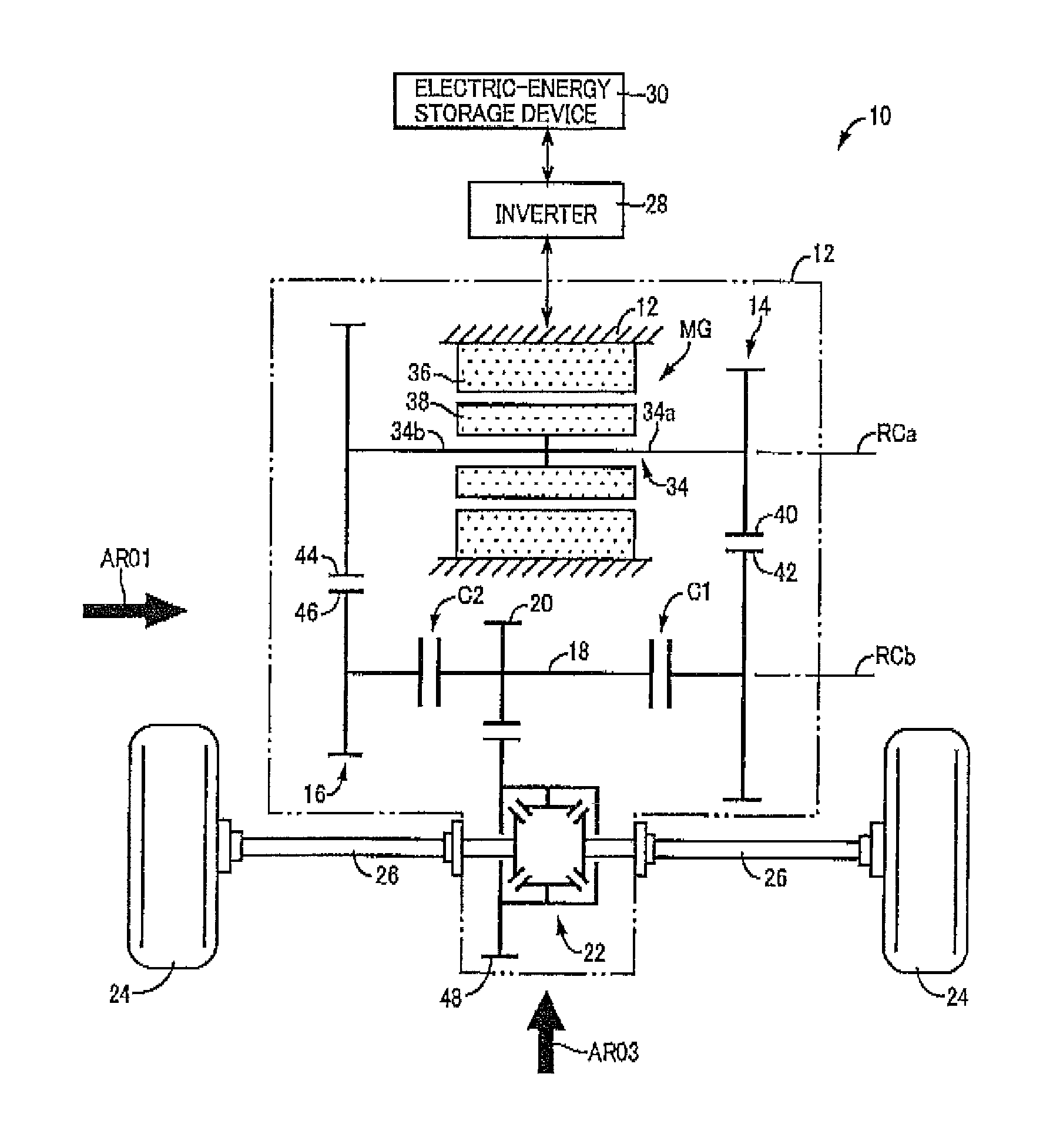
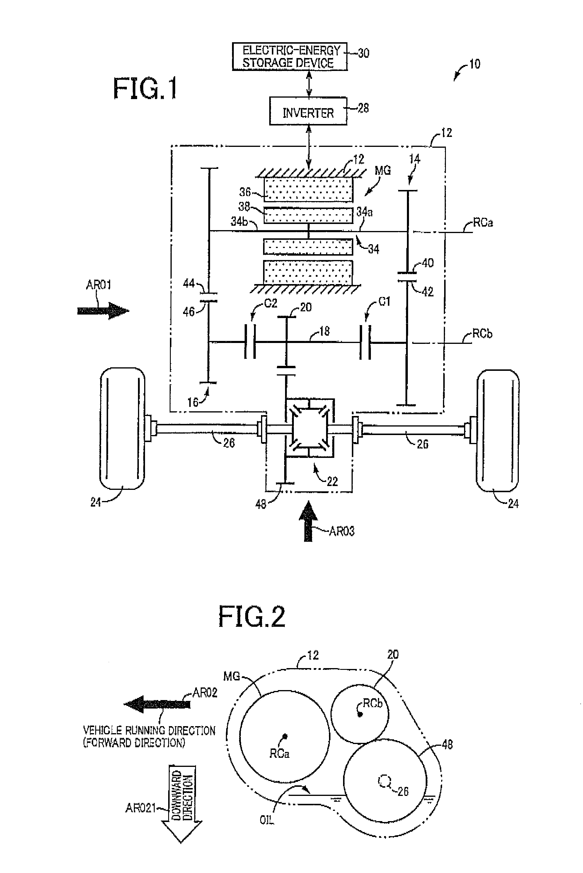
[0027]FIG. 1 is the schematic view for explaining a vehicular drive system 10 constructed according to the principle of this invention. In FIG. 1, RCa represents a first axis which is an axis of rotation of an electric motor MG, while RCb represents a second axis which is an axis of rotation of a counter shaft 18. These first axis RCa and second axis RCb, and axes of drive axles 26 are shown in the same plane in the plan view of FIG. 1, which do not lie in a single plane, as is apparent from FIG. 2 referred to later.

[0028]As shown in FIG. 1, the vehicular drive system 10 has a stationary member in the form a of a transaxle casing (T / A casing) 12 (hereinafter referred to as “casing 12”) fixed to the body of a vehicle by bolts or any other fixing means. Within the casing 12 serving as a housing of the vehicular drive system 10, there are disposed the electric motor MG, a first transmission portion 14, a second transmission portion 16, a first clutch C1, a second clutch C2, the counter...

second embodiment

[0044]Aspects of the present embodiment (second embodiment) which are identical with those of the above-described first embodiment will not be described, and only those aspects of the present invention which are different from the first embodiment will be described. FIG. 4 is the schematic view for explaining a vehicular drive system 110 according to the present embodiment, and FIG. 5 is the cross sectional view showing a portion of the vehicular drive system 110 in which the first clutch C1 is disposed, namely, a portion of the vehicular drive system 110 enclosed by a one-dot chain line A01 in FIG. 4. The vehicular drive system 110 according to the present embodiment is basically identical in construction with the vehicular drive system 10 according to the first embodiment, except in the positions of the first clutch C1 and the second clutch C2, as is apparent by comparison of the arrangement of FIG. 4 with that of FIG. 1.

[0045]Described in detail, the first clutch C1 provided in t...

third embodiment

[0048]Aspects of the present embodiment (third embodiment) which are identical with those of the above-described second embodiment will not be described, and only those aspects of the present invention which are different from the second embodiment will be described. FIG. 6 is the schematic view for explaining a vehicular drive system 210 according to the present embodiment. While the electric motor MG is shown in FIG. 6 in a simpler manner than in FIGS. 1 and 4, the electric motor MG provided in the vehicular drive system 210 is identical with the electric motor MG provided in the above-described vehicular drive systems 10, 110. The vehicular drive system 210 according to the present embodiment is different from the vehicular drive system 110 according to the second embodiment, in that each of a first transmission portion 214 and a second transmission portion 216 has a plurality of speed positions, as is apparent by comparison of the arrangement of FIG. 6 with that of FIG. 4.

[0049]...


PUM


Abstract

A vehicular drive system provided with an electric motor for generating a drive force to be transmitted to drive wheels, includes: the electric motor including an output rotary member having opposite end portions from which the drive force of the electric motor is transmitted to the drive wheels; two power connecting / disconnecting devices respectively configured to selectively connect and disconnect each of the opposite end portions of the output rotary member to and from the drive wheels; and the two power connecting / disconnecting devices being controlled to selectively connect the opposite end portions of the output rotary member to the drive wheels, for thereby changing a ratio of rotating speeds of the drive wheels to an operating speed of the electric motor.

Description

TECHNICAL FIELD[0001]The present invention relates to a mechanical arrangement of a vehicular drive system including an electric motor for generating a drive force to be transmitted to drive wheels.BACKGROUND ART[0002]There is known a vehicular drive system including an electric motor for generating a drive force to be transmitted to drive wheels. Patent Document 1 discloses an example of such a vehicular drive system in the form of a drive system for an electric vehicle. In the electric vehicle drive system disclosed in this Patent Document 1, an output rotary member of the above-indicated electric motor, namely, an output shaft of the electric motor is connected at one end portion thereof to the drive wheels through a speed reducing mechanism. The output shaft of the electric motor is not connected at the other end portion. That is, the drive force of the above-described electric motor is transmitted from only the above-indicated one end portion to the drive wheels, but is not tra...

Claims


Application Information

Patent Timeline
Patent Type & Authority Patents(United States)
IPC IPC(8): F16H48/30
CPCF16H2200/0043F16H3/006Y02T10/70F16H2200/0034B60L15/2054B60K17/356B60K1/00F16H3/093B60K17/02F16H2200/0021F16H2200/0052B60L11/00F16H3/089B60K2001/001B60K17/06Y02T10/7275Y02T10/72B60L50/00Y02T10/64
Inventor SATO, AKIHIROISHII, HIROYUKI
Owner TOYOTA JIDOSHA KK
Learn More