Vehicular drive system
a technology of mechanical arrangement and vehicular drive, which is applied in the direction of electric propulsion mounting, transportation and packaging, and the etc., can solve the problems of difficult installation of electric motors, the inability of electric motors b>900/b> to be installed at the desired position on the vehicle, etc., to achieve a high degree of efficiency, reduce the degree of design limitation, and improve the effect of cooling
- Summary
- Abstract
- Description
- Claims
- Application Information
AI Technical Summary
Benefits of technology
Problems solved by technology
Method used
Image
Examples
first embodiment
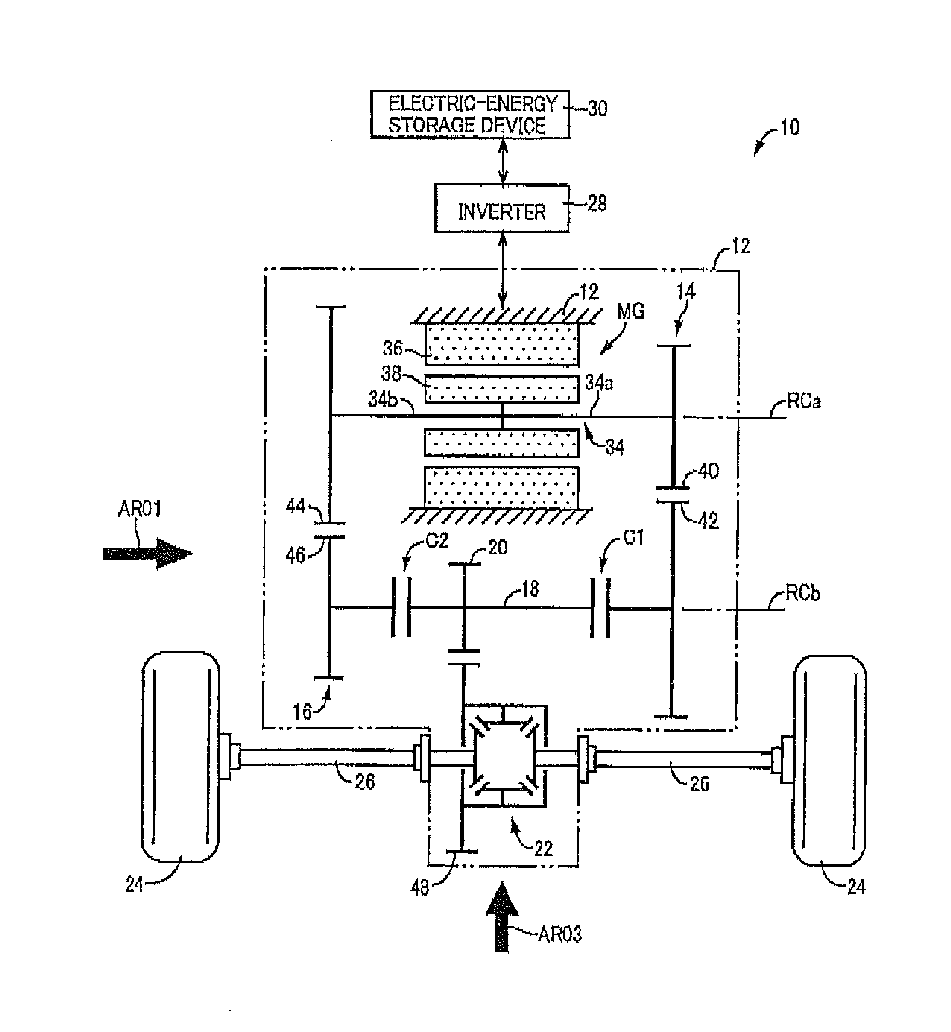
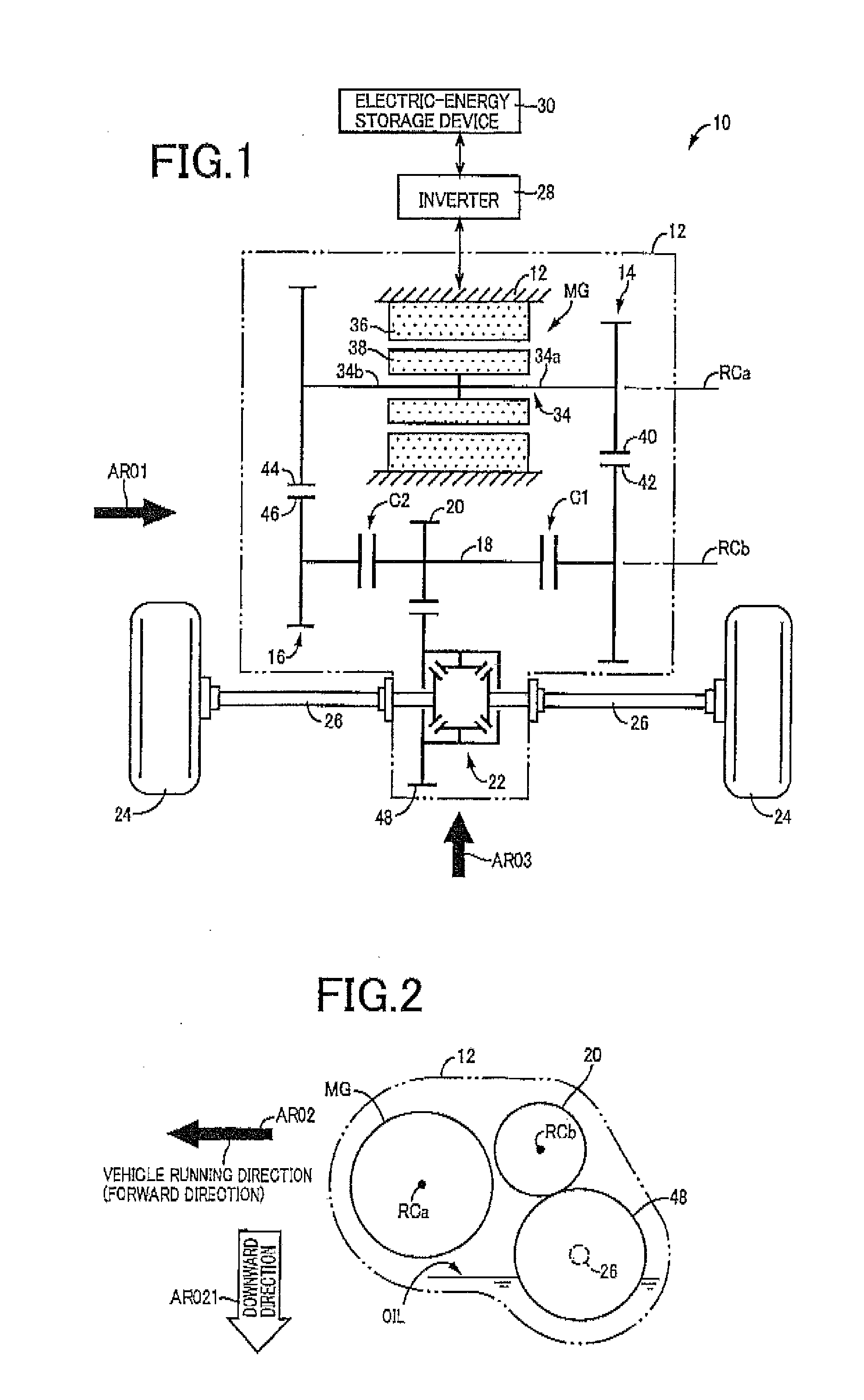
[0027]FIG. 1 is the schematic view for explaining a vehicular drive system 10 constructed according to the principle of this invention. In FIG. 1, RCa represents a first axis which is an axis of rotation of an electric motor MG, while RCb represents a second axis which is an axis of rotation of a counter shaft 18. These first axis RCa and second axis RCb, and axes of drive axles 26 are shown in the same plane in the plan view of FIG. 1, which do not lie in a single plane, as is apparent from FIG. 2 referred to later.
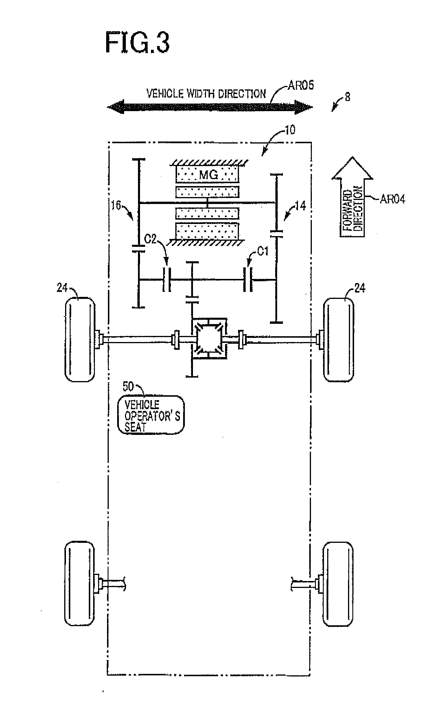
[0028]As shown in FIG. 1, the vehicular drive system 10 has a stationary member in the form of a transaxle casing (T / A casing) 12 (hereinafter referred to as “casing 12”) fixed to the body of a vehicle by bolts or any other fixing means. Within the casing 12 serving as a housing of the vehicular drive system 10, there are disposed the electric motor MG, a first transmission portion 14, a second transmission portion 16, a first clutch C1, a second clutch C2, the counter s...
second embodiment
[0048]Aspects of the present embodiment (second embodiment) which are identical with those of the above-described first embodiment will not be described, and only those aspects of the present invention which are different from the first embodiment will be described. FIG. 4 is the schematic view for explaining a vehicular drive system 110 according to the present embodiment, and FIG. 5 is the cross sectional view showing a portion of the vehicular drive system 110 in which the first clutch C1 is disposed, namely, a portion of the vehicular drive system 110 enclosed by a one-dot chain line A01 in FIG. 4. The vehicular drive system 110 according to the present embodiment is basically identical in construction with the vehicular drive system 10 according to the first embodiment, except in the positions of the first clutch C1 and the second clutch C2, as is apparent by comparison of the arrangement of FIG. 4 with that of FIG. 1.
[0049]Described in detail, the first clutch C1 provided in t...
third embodiment
[0052]Aspects of the present embodiment (third embodiment) which are identical with those of the above-described second embodiment will not be described, and only those aspects of the present invention which are different from the second embodiment will be described. FIG. 6 is the schematic view for explaining a vehicular drive system 210 according to the present embodiment. While the electric motor MG is shown in FIG. 6 in a simpler manner than in FIGS. 1 and 4, the electric motor MG provided in the vehicular drive system 210 is identical with the electric motor MG provided in the above-described vehicular drive systems 10, 110. The vehicular drive system 210 according to the present embodiment is different from the vehicular drive system 110 according to the second embodiment, in that each of a first transmission portion 214 and a second transmission portion 216 has a plurality of speed positions, as is apparent by comparison of the arrangement of FIG. 6 with that of FIG. 4.
[0053]...
PUM
 Abstract
Description
Claims
Application Information
 - R&D
- Intellectual Property
- Life Sciences
- Materials
- Tech Scout
- Unparalleled Data Quality
- Higher Quality Content
- 60% Fewer Hallucinations
Browse by: Latest US Patents, China's latest patents, Technical Efficacy Thesaurus, Application Domain, Technology Topic, Popular Technical Reports.
© 2025 PatSnap. All rights reserved.Legal|Privacy policy|Modern Slavery Act Transparency Statement|Sitemap|About US| Contact US: help@patsnap.com


