Leadframe structure for concentrated photovoltaic receiver package
a technology of photovoltaic receiver and lead frame, which is applied in the direction of semiconductor devices, semiconductor/solid-state device details, electrical equipment, etc., can solve the problem of significant cost benefits in relation to the fabrication process
- Summary
- Abstract
- Description
- Claims
- Application Information
AI Technical Summary
Benefits of technology
Problems solved by technology
Method used
Image
Examples
first embodiment
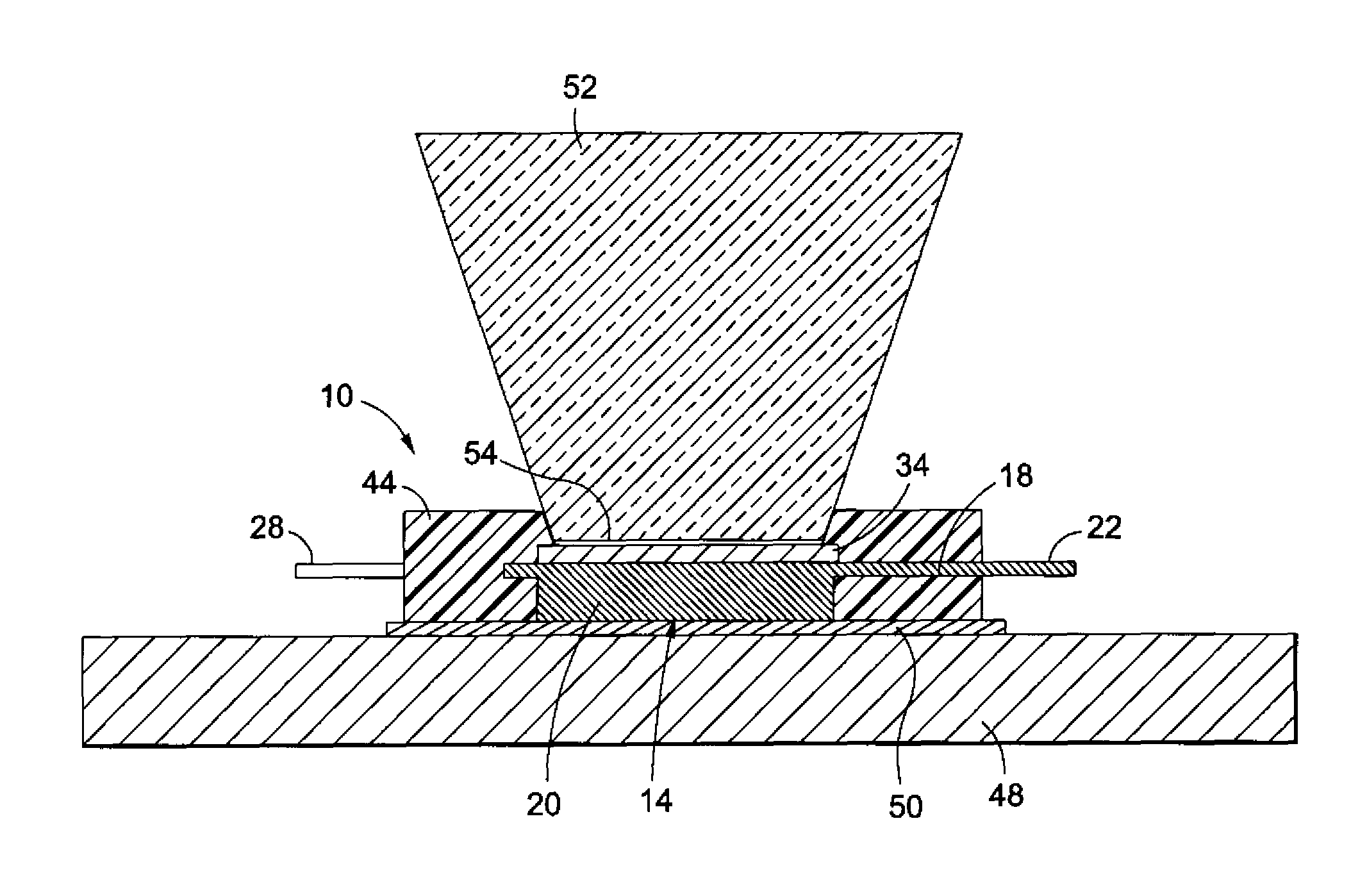
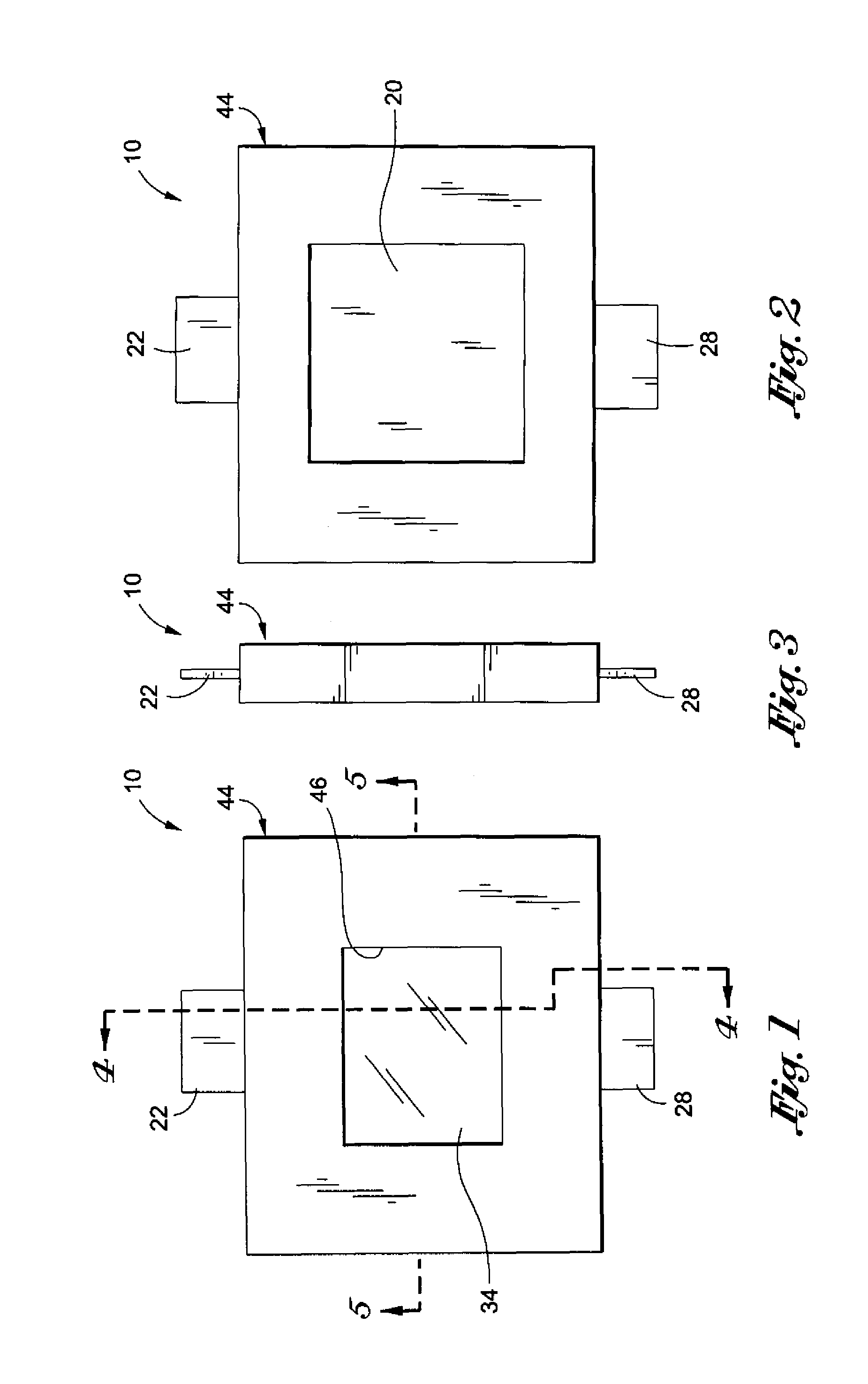
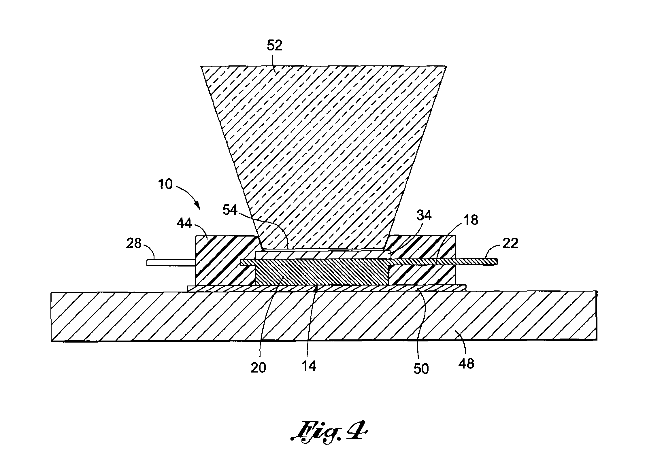
[0038]Referring now to the drawings wherein the showings are for purposes of illustrating preferred embodiments of the present invention only, and not for purposes of limiting the same, FIGS. 1-5 and 6 depict a CPV module 10 constructed in accordance with the present invention. As best seen in FIG. 6, the module 10 comprises a leadframe 12 which is preferably fabricated from a conductive metal material, such as copper. The leadframe 12 includes a first section 14 and a separate second section 16. The first section 14 includes a generally rectangular base portion 18 which defines opposed pairs of longitudinally and laterally extending side edges. In addition to the base portion 18, the first section 14 includes a generally square die pad portion 20 which protrudes from one of the longitudinally extending side edges of the base portion 18. Extending from the approximate center of the longitudinally extending side edge of the base portion 18 opposite the side edge from which the die pa...
second embodiment
[0048]Referring now to FIGS. 8 and 9, there is shown a CPV module 100 constructed in accordance with the present invention. The module 100 comprises a leadframe 112 which is preferably fabricated from a conductive metal material, such as copper. The leadframe 112 includes a first (bottom) section 114 and a separate second (top) section 116. The first section 114 includes a generally quadrangular die pad portion 120 which defines opposed, generally planar top and bottom surfaces. In addition to the die pad portion 120, the first section 114 includes a flange portion 118 which extends generally perpendicularly relative to the top surface of the die pad portion 120 along one of the side edges thereof. Extending perpendicularly from the approximate center of the distal edge of the flange portion 118 is a generally quadrangular connector portion 122 of the first section 114. Thus, in the first section 114, the die pad portion 120 and the connector portion 122 extend along respective ones...
third embodiment
[0056]Referring now to FIG. 12, there is shown a CPV module 200 constructed in accordance with the present invention. The CPV module 200 is substantially similar to the above-described CPV module 100, with only the distinctions between the CPV modules 200, 100 being described below.
[0057]The sole distinction between the CPV modules 200, 100 lies in the second section 116 of the leadframe 112 included in the module 200 further defining a raised lip or edge 164. As seen in FIGS. 12 and 13, the edge 164 has a three-sided configuration, and extends along the inner edges of the prong portions 136 of the second section 116, as well as a portion of the inner edge of the base portion 124 thereof. The raised edge 164 included with the first section 116 of the leadframe 112 of the module 200 is used to define an alignment feature which properly aligns a light concentrating device such as a light guide or optical rod over the receiver die 134 of the module 200. Additionally, in the module 200,...
PUM
 Abstract
Description
Claims
Application Information
 - R&D
- Intellectual Property
- Life Sciences
- Materials
- Tech Scout
- Unparalleled Data Quality
- Higher Quality Content
- 60% Fewer Hallucinations
Browse by: Latest US Patents, China's latest patents, Technical Efficacy Thesaurus, Application Domain, Technology Topic, Popular Technical Reports.
© 2025 PatSnap. All rights reserved.Legal|Privacy policy|Modern Slavery Act Transparency Statement|Sitemap|About US| Contact US: help@patsnap.com


