Optical fiber

a technology of optical fiber and fiber, applied in the field of optical fiber, can solve the problems of large propagation loss, inability to achieve both propagation loss prevention and low propagation loss, and inability to achieve low propagation loss, reduce light quantity, and prevent the effect of resin coating combustion

Active Publication Date: 2014-04-01
SUMITOMO ELECTRIC IND LTD
View PDF76 Cites 6 Cited by
  • Summary
  • Abstract
  • Description
  • Claims
  • Application Information

AI Technical Summary

Benefits of technology

The present invention provides an optical fiber that prevents the resin coating from catching fire due to leaked light, while also minimizing the loss of optical power during transmission. This is achieved by a leakage reduction portion in the physical cladding of the fiber that reduces the amount of leaked light. The leakage reduction portion does not affect the transmission characteristics of the light within the core region of the fiber. The optical fiber can be bent at a small radius without causing combustion of the resin coating. The reduction in leaked light is achieved through deflection control, either by confinement of the leaked light or by increasing scattering of the leaked light. The refractive index of the leakage reduction portion can be set higher than the refractive indices of the optical cladding and the physical cladding to further enhance deflection control.

Problems solved by technology

For example, when bending with a small radius of curvature (hereinafter referred to as “small-radius bending”) is applied to an optical fiber during high-power light propagation, light leaking from the core region (light propagating toward a side face of the optical fiber arising from small-radius bending) reaches the resin coating, with the possibility that combustion of the resin coating might be caused.
However, in all such trench fibers and hole-assisted fibers, propagation losses are larger than in standard SMFs, and in the prior art it has not been possible to achieve both prevention of resin coating combustion, and low propagation losses.
On the other hand, the steep refractive index reduced portion itself in proximity to the core region, or the interface at which the steep reduction in refractive index occurs, becomes a cause of large propagation losses relative to the core region or similar, so that propagation losses in trench fibers and hole-assisted fibers are larger than in standard SMFs not having refractive index reduced portions formed by trenches or holes.
This inability to achieve both prevention of resin coating combustion and low-loss light transmission may become a major obstacle to the future realization of long-haul, large-capacity transmission.

Method used


Image

  • Optical fiber
  • Optical fiber
  • Optical fiber

Examples


first embodiment

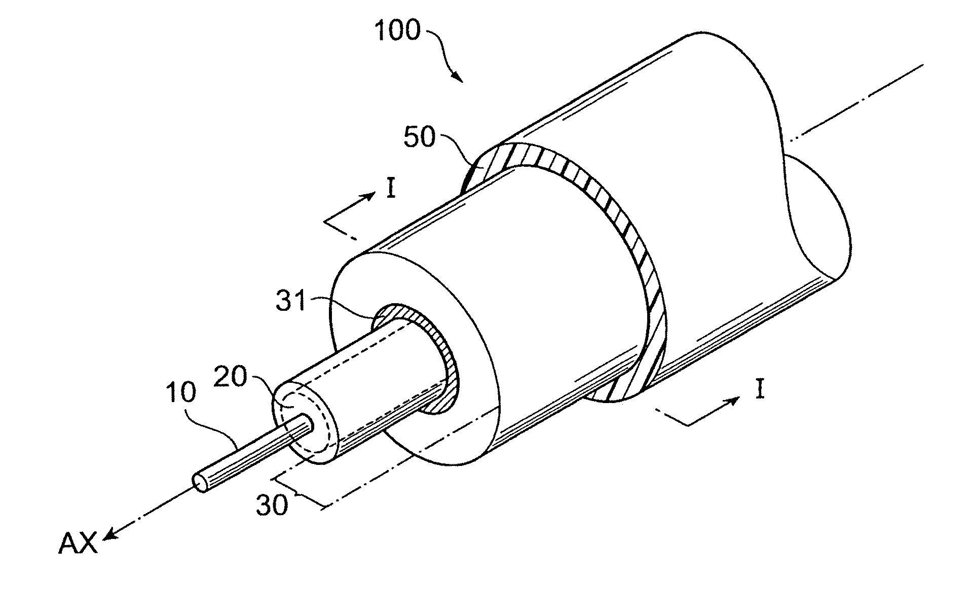
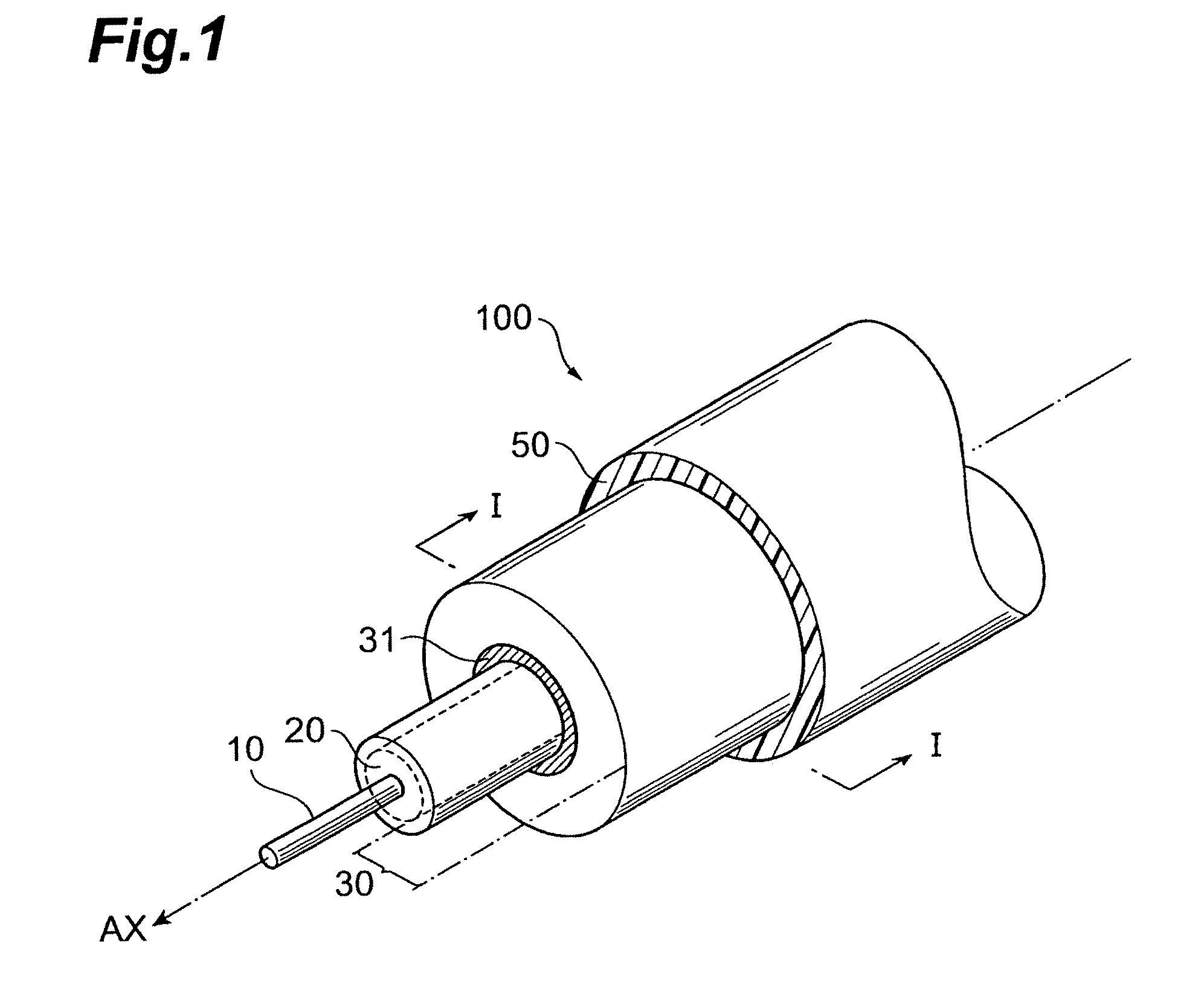
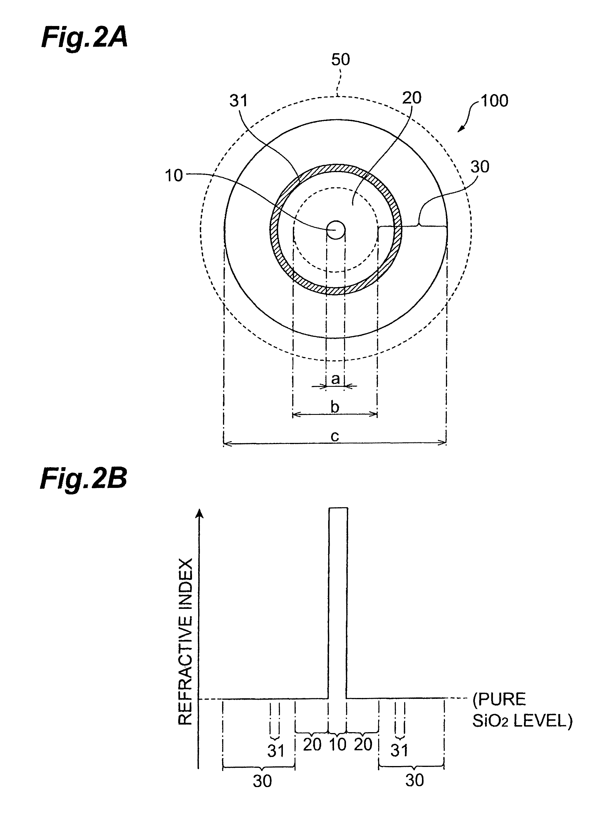
[0028]FIG. 1 is a perspective view showing the schematic structure of a first embodiment of an optical fiber according to the present invention. FIG. 2A shows the cross-sectional structure of the optical fiber according to the first embodiment orthogonal to the optical axis AX, and FIG. 2B is the refractive index profile thereof. The schematic structure of the optical fiber shown in FIG. 1 is a schematic structure common to the second through fourth embodiments explained below.

[0029]As shown in FIG. 1, the optical fiber 100 according to the first embodiment comprises a core region 10 extending along the optical axis AX, a cladding region provided on an outer periphery of the core region 10, and a resin coating (UV (ultraviolet) curable resin) 50 provided on an outer periphery of the cladding region. The cladding region is constituted by an optical cladding 20 provided directly on an outer periphery of the core region 10, and a physical cladding 30 provided on an outer periphery of t...

second embodiment

[0037]FIGS. 4A to 4D show the schematic structure of a second embodiment of an optical fiber according to the present invention. The second embodiment performs leaked light deflection control by confining leaked light within a region on the inside of the leakage reduction portion. FIG. 4A is a cross-sectional view showing the structure of the optical fiber 200 according to the second embodiment, and is equivalent to a cross-section along line I-I in FIG. 1. FIG. 4B is a refractive index profile of the optical fiber 200, and shows first means for achieving leaked light deflection control in the second embodiment. FIG. 4C is an enlarged view of the portion B in FIG. 4A, and shows second means for achieving leaked light deflection control in the second embodiment. FIG. 4D is an enlarged view of the portion B in FIG. 4A, and shows third means for achieving leaked light deflection control in the second embodiment.

[0038]The optical fiber 200 according to the second embodiment comprises a ...

third embodiment

[0048]FIGS. 5A to 5C show the schematic structure of a third embodiment of an optical fiber according to the present invention. In the third embodiment, leaked light deflection control is performed by causing propagation, in the leakage reduction portion, of the leaked light which has arrived from the core region. FIG. 5A is a cross-sectional view showing the structure of the optical fiber 300 according to the third embodiment, and is equivalent to the cross-section along line I-I in FIG. 1. FIG. 5B is a refractive index profile of the optical fiber 300, and shows first means for achieving leaked light deflection control in the third embodiment. FIG. 5C is an enlarged view of the portion C in FIG. 5A, and shows second means for achieving leaked light deflection control in the third embodiment.

[0049]The optical fiber 300 according to the third embodiment comprises a core region extending along the optical axis AX, a cladding region provided on an outer periphery of the core region 10...


PUM


Abstract

The present invention relates to an optical fiber having a structure to enable both prevention of resin coating combustion due to leaked light, and low-loss light transmission. The optical fiber comprises a core region, and a cladding region. The cladding region is constituted by an optical cladding which affects the transmission characteristics of light propagating in the core region, and a physical cladding which does not affect the transmission characteristics of light propagating in the core region. Particularly, a leakage reduction portion is provided in the physical cladding so as to surround an outer periphery of the core region through the optical cladding. The leakage reduction portion functions to suppress propagation of the leaked light propagating from the core region toward outside the cladding region.

Description

CROSS-REFERENCE TO RELATED APPLICATION[0001]This application is a divisional of U.S. application Ser. No. 12 / 689,596 filed Jan. 19, 2010 which claims priority from Japanese Patent Application No. 2009-009095 filed Jan. 19, 2009.BACKGROUND OF THE INVENTION[0002]1. Field of the Invention[0003]The present invention relates to an optical fiber which is suitable as a transmission medium for optical communication, and in particular relates to an optical fiber having excellent high-power endurance.[0004]2. Related Background of the Invention[0005]At present, optical fiber communication networks are being expanded from trunk lines to ordinary homes, and are gaining wide recognition as FTTH (Fiber To The Home) services. Nearly all the optical fibers employed in such communication networks are silica-based fibers; by adding a refractive index increaser such as for example GeO2 to the core region, full-reflection optical waveguide structures having a refractive index difference, with the cladd...

Claims


Application Information

Patent Timeline
Patent Type & Authority Patents(United States)
IPC IPC(8): G02B6/032G02B6/036
CPCG02B6/02342G02B6/03694G02B6/02G02B6/03633
Inventor SASAOKA, EISUKE
Owner SUMITOMO ELECTRIC IND LTD
Why Eureka
Try Eureka