Semiconductor devices having reduced substrate damage and associated methods

a semiconductor and substrate technology, applied in semiconductor devices, solid-state devices, basic electric elements, etc., can solve the problems of laser damage having detrimental effects on the semiconductor material, introducing laser damage into the semiconductor material, and reducing minority carrier lifetime and mobility of minority carriers, so as to achieve the effect of increasing operating performan

Active Publication Date: 2014-04-15
SIONYX
View PDF107 Cites 14 Cited by
  • Summary
  • Abstract
  • Description
  • Claims
  • Application Information

AI Technical Summary

Benefits of technology

[0003]The present disclosure provides optoelectronic devices, materials, and associated methods having increased operating performance. In one aspect, for example, an optoelectronic device is provided. Such a device can include a semiconductor material, a first doped region in the semiconductor material, a second doped region in the semiconductor material forming a junction with the first doped region, and a laser processed region associated with the junction. The laser processed region is positioned to interact with electromagnetic radiation. Additionally, at least a portion of a region of laser damage from the laser processed region has been removed such that the optoelectronic device has an open circuit voltage of from about 500 mV to about 800 mV. In another aspect, laser damage from the laser processed region has been removed such that the optoelectronic device has an open circuit voltage of from about 600 mV to about 700 mV.

Problems solved by technology

In some cases, however, such a laser texturing process can introduce laser damage into the semiconductor material as the laser is ablating, melting, and allowing the semiconductor to solidify.
Laser damage can have detrimental effects on the semiconductor material, such as, for example, lower minority-carrier lifetime and lower majority-carrier mobility.
For many optoelectronic devices, this laser damage to the crystalline structure of the semiconductor can result in increased dark current and / or reduced quantum efficiency and device performance.
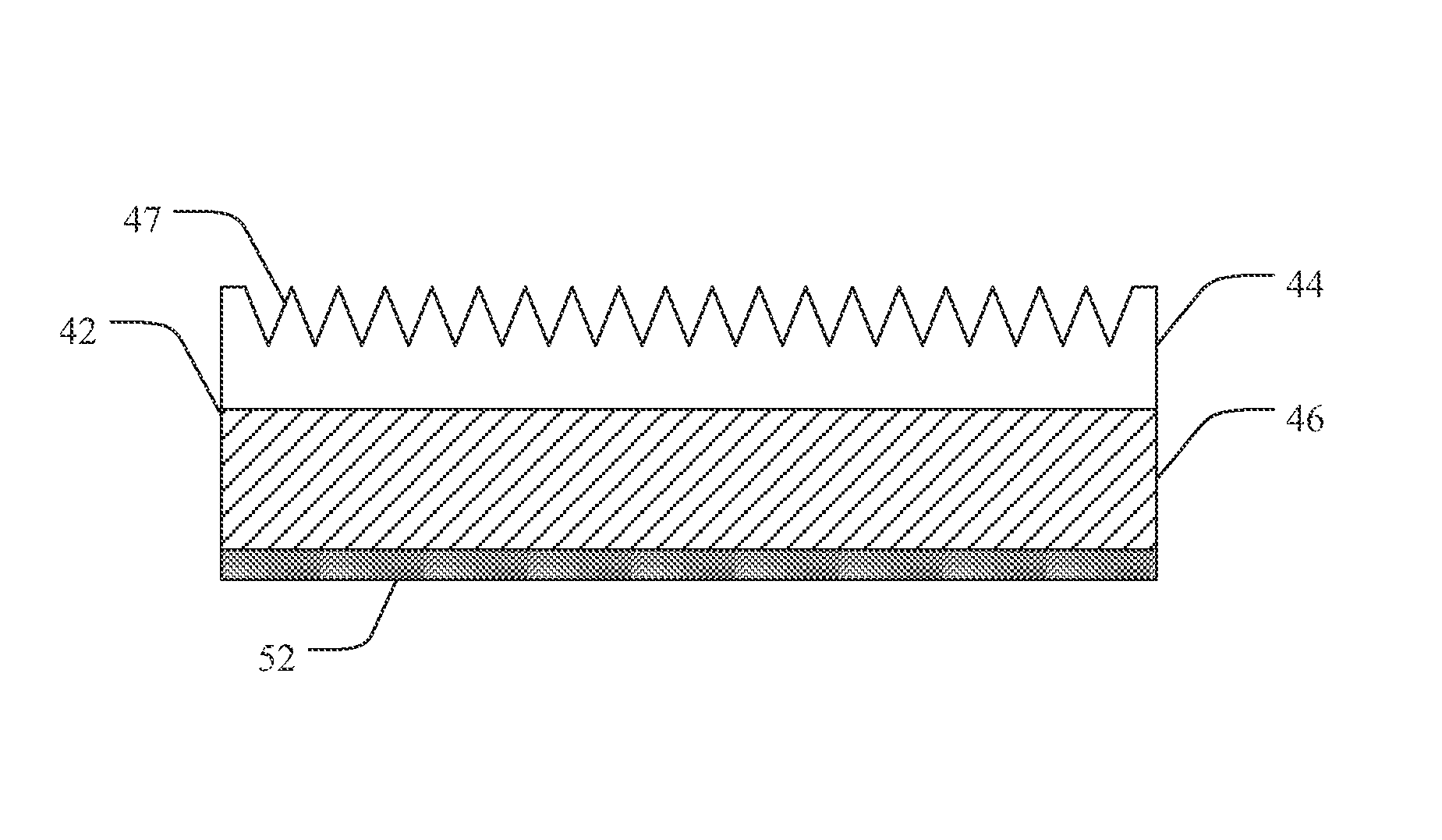
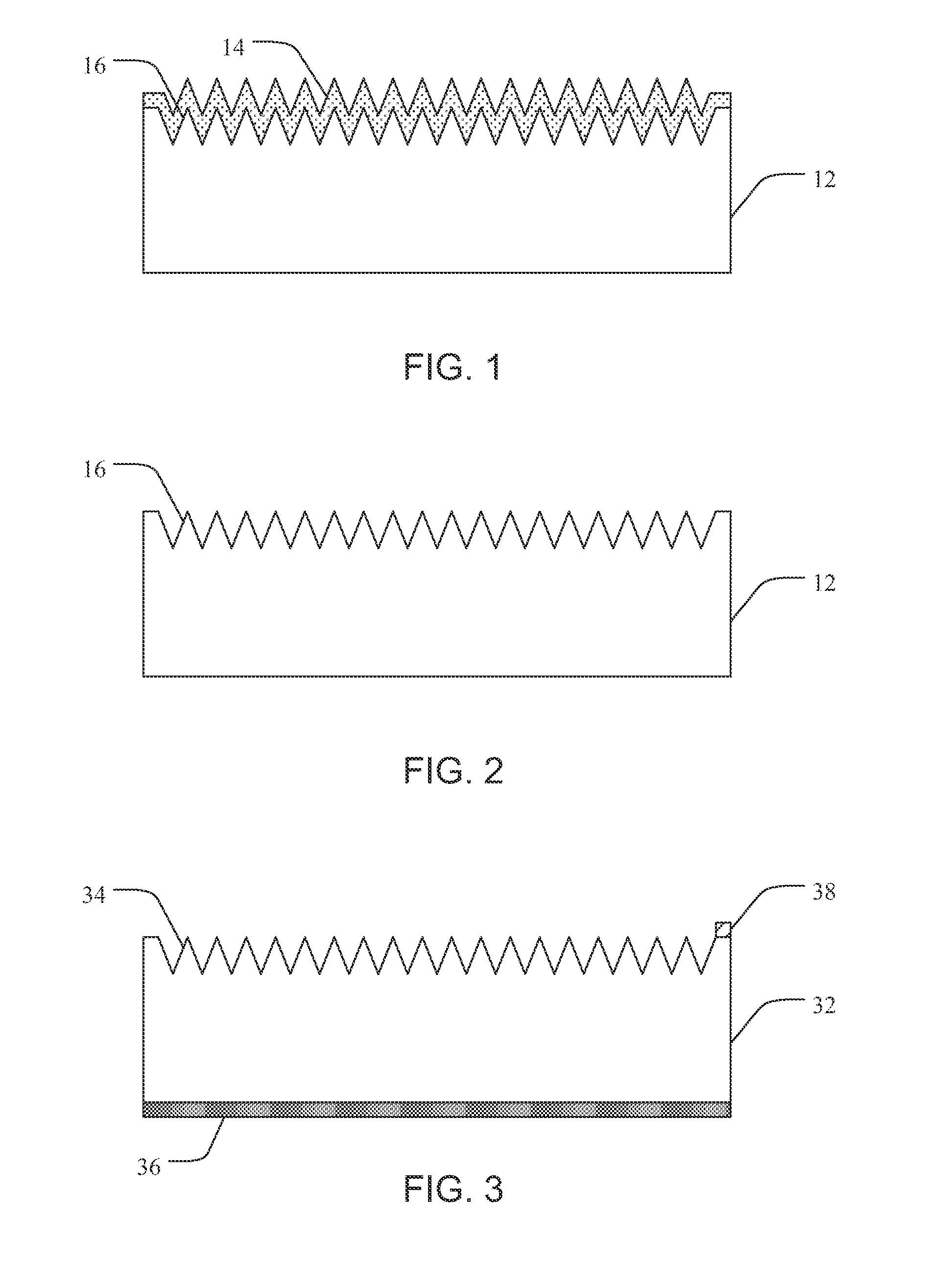
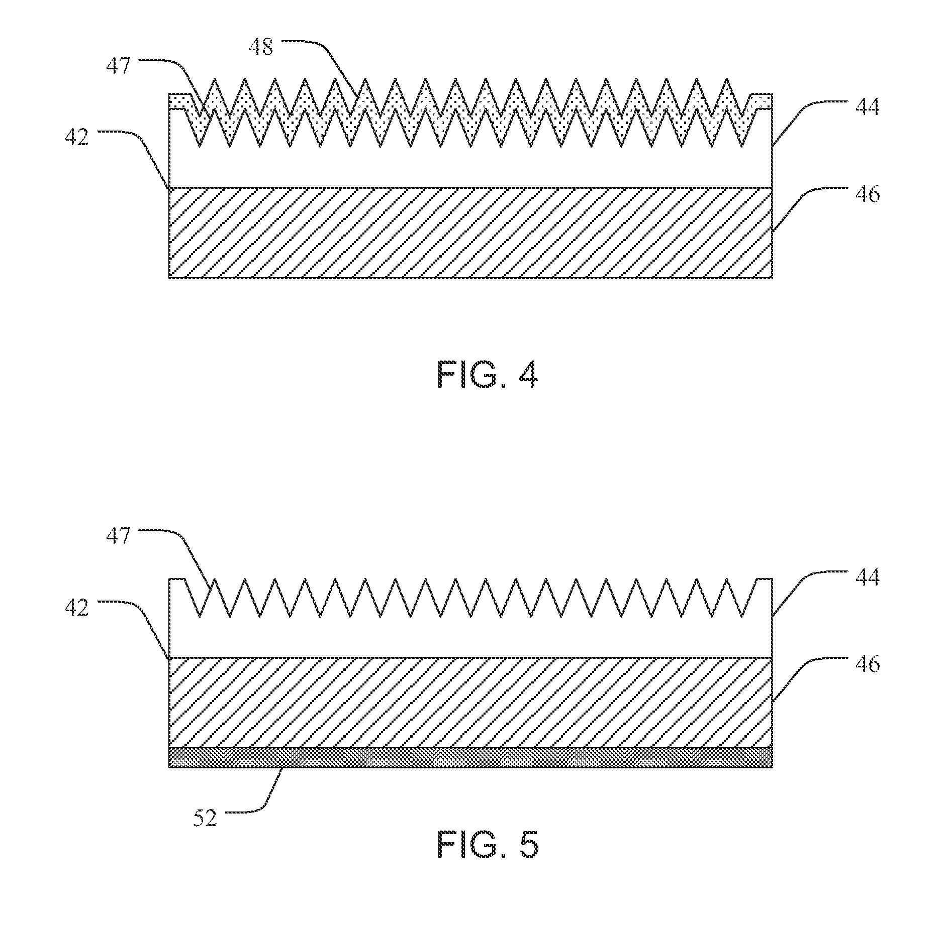
The textured surface can include a laser damaged region 14, where the laser processing has generated undesirable defects in the crystal lattice of the semiconductor material that can result in lower minority-carrier lifetime and lower majority-carrier mobility.

Method used


Image

  • Semiconductor devices having reduced substrate damage and associated methods
  • Semiconductor devices having reduced substrate damage and associated methods
  • Semiconductor devices having reduced substrate damage and associated methods

Examples


Embodiment Construction

[0013]Before the present disclosure is described herein, it is to be understood that this disclosure is not limited to the particular structures, process steps, or materials disclosed herein, but is extended to equivalents thereof as would be recognized by those ordinarily skilled in the relevant arts. It should also be understood that terminology employed herein is used for the purpose of describing particular embodiments only and is not intended to be limiting.

DEFINITIONS

[0014]The following terminology will be used in accordance with the definitions set forth below.

[0015]It should be noted that, as used in this specification and the appended claims, the singular forms “a,” and, “the” include plural referents unless the context clearly dictates otherwise. Thus, for example, reference to “a dopant” includes one or more of such dopants and reference to “the layer” includes reference to one or more of such layers.

[0016]As used herein, the terms “light” and “electromagnetic radiation” ...


PUM


Abstract

Optoelectronic devices, materials, and associated methods having increased operating performance are provided. In one aspect, for example, an optoelectronic device can include a semiconductor material, a first doped region in the semiconductor material, a second doped region in the semiconductor material forming a junction with the first doped region, and a laser processed region associated with the junction. The laser processed region is positioned to interact with electromagnetic radiation. Additionally, at least a portion of a region of laser damage from the laser processed region has been removed such that the optoelectronic device has an open circuit voltage of from about 500 mV to about 800 mV.

Description

PRIORITY DATA[0001]This application claims the benefit of U.S. Provisional Patent Application Ser. No. 61 / 425,634, filed on Dec. 21, 2010, which is incorporated herein by reference.BACKGROUND[0002]The interaction of light with semiconductor devices is at the core of some important innovations. Optoelectronic devices, such as photovoltaics, photodiodes, and imagers, are used in various technologies, such as for example, solar cells, digital cameras, optical mice, video cameras, cell phones, and the like. Typically, many semiconductor photodetecting devices are formed from a silicon material. When thick enough, silicon is known to absorb a majority of incident visible light having wavelengths in the range of about 300 nm to 900 nm. These factors, combined with its low cost, abundant supply, non-toxicity and the quantum efficiency in the visible spectrum make silicon a top choice for light detecting. However, because of its indirect bandgap, one major limitation to silicon for optical ...

Claims


Application Information

Patent Timeline
Patent Type & Authority Patents(United States)
IPC IPC(8): H01L31/06
CPCY02E10/50H01L31/1032H01L31/03529H01L31/1035H01L31/103H01L31/02363H01L31/0236H01L31/0256H01L31/0352H01L31/035218H01L31/18Y02E10/541H01L31/02366H01L31/02966H01L31/03046H01L31/032H01L31/0368H01L31/03923H01L31/03925
Inventor VINEIS, CHRISTOPHERCAREY, JAMESLI, XIA
Owner SIONYX
Why Eureka
Try Eureka