
Non-curvilinear LED luminaries

a technology of led luminaires and non-curvilinear lines, which is applied in the field of led lighting, can solve the problems of mercury exposure, inconvenient manufacturing and installation, and inefficient incandescent light bulbs, and achieve the effects of convenient manufacturing and installation, enhanced led lighting, and convenient and safe manufacturing

Active Publication Date: 2014-04-22
DVA HLDG LLC
View PDF18 Cites 62 Cited by
  • Summary
  • Abstract
  • Description
  • Claims
  • Application Information

AI Technical Summary

Benefits of technology

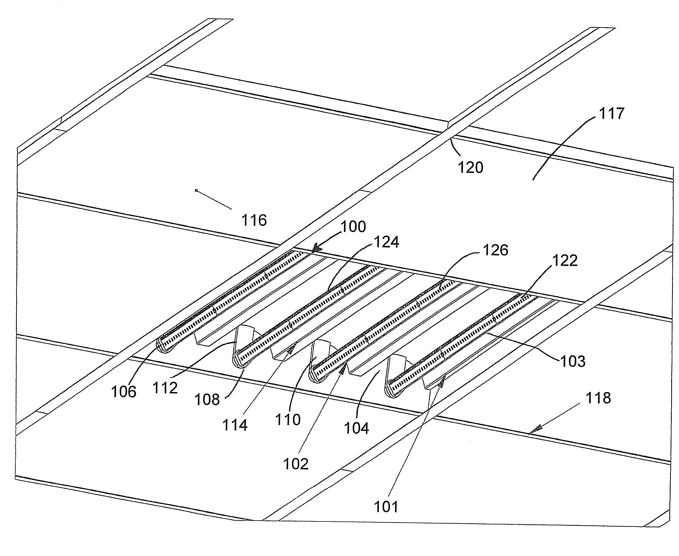
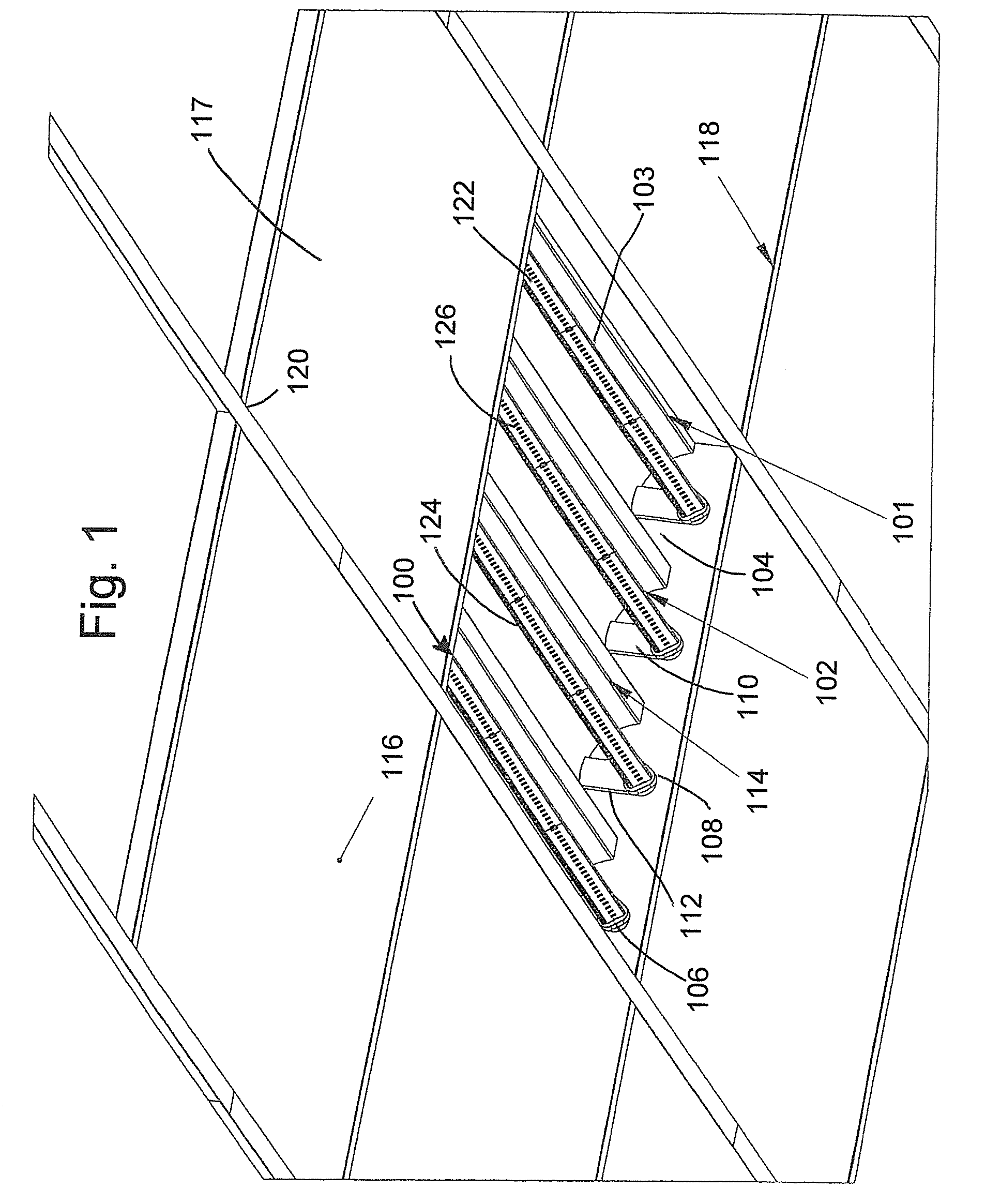
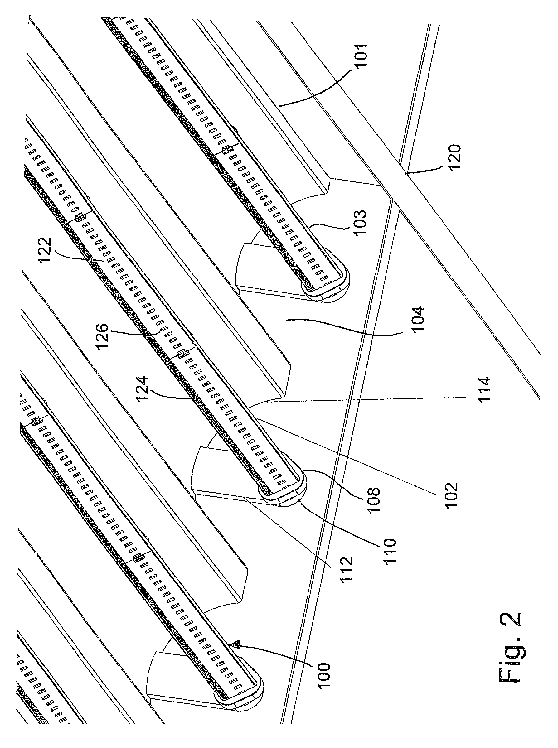
[0016]An improved light emitting diode (LED) illuminating assembly is provided with a novel multiple sided LED lighting bar, also referred to as a multi-sided LED light bar, comprising a non-curvilinear LED luminary for enhanced LED lighting. Advantageously, the inventive LED illuminating assembly with the novel multi-sided light bar is efficient, effective, economical, convenient and safe. Desirably, the user friendly LED illuminating assembly with the compact multi-sided light bar produces outstanding illumination, is easy to manufacture and install, and has a long life span. The improved LED illuminating assembly and attractive multi-sided light bar are also reliable, durable and impact and breakage resistant.
[0017]The improved LED illuminating assembly can feature: a multi-sided light bar, such as with two, three, four or five sides; an internal non-switching driver; a scalable length; and an emitter count optimized for efficiency. The improved LED luminary assembly can also feature: parallel-series wiring; a no-wire design using a unique end cap design; a lens cover cap per design requirements to modify the beam angle; and redundancy in the driver.
[0018]There are many advantages of the inventive LED illuminating assembly with a novel multi-sided LED lighting bar comprising a non-curvilinear LED luminary versus conventional LED lighting.

Problems solved by technology

Incandescent light bulbs, however, are very inefficient, as over 98% of its energy input is emitted and generated as heat.
While the heat generated by fluorescent lamps is much less than its incandescent counterpart, energy is still lost in generating the UV light and converting UV light into visible light.
If the lamp breaks, exposure to mercury can occur.
Some fluorescent lights flicker and the quality of the fluorescent light tends to be a harsh white due to the lack of a broad band of frequencies.
Most fluorescent lights are not compatible with dimmers.
With incandescent bulbs, the cost of replacement bulbs and the labor expense and time needed to replace them can be significant especially where there are a large number of incandescent bulbs.
For office buildings and high rise buildings, maintenance costs to replace bulbs can be expensive and can be substantially decreased with LED lighting.
Incandescent bulbs, however, operate at about 20% efficiency with 80% of the electrical energy is lost as heat.
In many countries incandescent lighting for homes and offices is no longer available and building regulations require new premises to use LED lighting.
Conventional prior art LED lighting which is powerful enough for room lighting, however, is relatively expensive and require more precise current and heat management than fluorescent lamp sources of comparable output.
Furthermore, conventional LED lighting can have a higher capital cost than other types of lighting and LED light tends to be directional with small areas of illumination.
Moreover, conventional LED luminaries suffer from drawbacks due to a lack of lumen output and less than desirable light dispersion.
Individually and combined, these aspects of conventional LED lighting can detract from efficient utilization of LED luminaries.

Method used


Image

  • Non-curvilinear LED luminaries
  • Non-curvilinear LED luminaries
  • Non-curvilinear LED luminaries

Examples


example

[0128]In this case, the emitter board: driver combination:

[0129]

A A AB B BC C C

if sub-driver A, B or C fails, or any emitter in the string, one third of the light goes away on that whole side. However, the real wiring would look like this:

[0130]

A B CC A BB C A

Now if or when one driver sub circuit fails, two-thirds of the light remains and the dead spot revolves around the lamp so there is only a dim spot and not a black out.

[0131]Parallel traces can be used in the preferred arrangement. The boards can be made with the traces pre-fabricated. Parallel traces are utilized when needed to get the power to the emitters in an electrically efficient way. The advantage of using parallel traces means is the emitters are all driven at exactly the same current and power level. That is not the case in most conventional designs. A further advantage of the arrangement of parallel-series wiring is that we can run our lighting at higher voltage and lower current so that it is more efficient regardle...


PUM


Abstract

An improved light emitting diode (LED) illuminating assembly is provided with a multiple sided LED lighting bar, also referred to as a multi-sided LED light bar, comprising a non-curvilinear LED luminary for enhanced LED lighting. The LED illuminating assembly can be used for overhead ceiling lighting, menu boards and other LED illuminating signs, as well as for other uses.

Description

BACKGROUND OF THE INVENTION[0001]This invention relates to lighting and, more particularly, to light emitting diode (LED) illumination.[0002]Over the years various types of illuminating assemblies and devices have been developed for indoor and / or outdoor illumination, such as torches, oil lamps, gas lamps, lanterns, incandescent bulbs, neon signs, fluorescent bulbs, halogen lights, and light emitting diodes. These conventional prior art illuminating assemblies and devices have met with varying degrees of success.[0003]Incandescent light bulbs create light by conducting electricity through a thin filament, such as a tungsten filament, to heat the filament to a very high temperature so that it glows and produces visible light. Incandescent light bulbs emit a yellow or white color. Incandescent light bulbs, however, are very inefficient, as over 98% of its energy input is emitted and generated as heat. A standard 100 watt light bulb emits about 1700 lumens, or about 17 lumens per watt....

Claims


Application Information

Patent Timeline
Patent Type & Authority Patents(United States)
IPC IPC(8): F21V21/005F21V5/04G09F13/04F21S8/04F21V29/00
CPCF21S8/04F21V5/04G09F13/04F21V29/00F21V21/005F21Y2103/003F21Y2101/02F21Y2111/005F21K9/17F21V19/001F21K9/20F21Y2103/10F21Y2115/10F21Y2113/00F21V29/89F21K9/272F21Y2107/30
Inventor MAY, MICHAEL, W.
Owner DVA HLDG LLC
Learn More