Fuel cell system

a fuel cell and system technology, applied in the field of fuel cell systems, can solve the problems of poor fuel economy, deterioration of the output voltage and mea, and difficulty in meeting the two requirements at the same time, so as to prevent the discharge of wasteful fuel gas, reduce the amount of fuel gas, and reduce the effect of fuel gas

Active Publication Date: 2014-04-22
TOYOTA JIDOSHA KK
View PDF29 Cites 1 Cited by
  • Summary
  • Abstract
  • Description
  • Claims
  • Application Information

AI Technical Summary

Benefits of technology

[0035]According to the first aspect of the present invention, since a substantially smaller amount of gas than the consumption of the fuel gas in the anode gas flow channel is discharged to the outside of the system, the impurity accumulated at the downstream end of the anode gas flow channel can be discharged to the outside of the system in small amounts while reducing the amount of fuel gas wastefully discharged, and therefore, accumulation of the impurity that can cause degradation of the performance of the fuel cell can be prevented. In addition, whether or not the impurity can be accumulated at the downstream end of the anode gas flow channel is determined based on the magnitude of the downstream flow of the impurity, and communication between the anode gas flow channel and the outside of the system is blocked until the magnitude of the downstream flow of the impurity reaches a predetermined switching criterion. Therefore, wasteful discharge of the fuel gas can be prevented.
[0036]According to the second aspect of the present invention, the downstream flow of the impurity in the anode gas flow channel can be indirectly detected by measuring the magnitude of the load on the fuel cell. That is, a sensor dedicated to direct detection of the flow of the impurity is not needed.
[0037]According to the third aspect of the present invention, the downstream flow of the impurity in the anode gas flow channel can be indirectly detected by measuring the physical quantity relating to the flow rate of the fuel gas in the anode gas flow channel and the physical quantity relating to the diffusion rate of the impurity in the anode gas flow channel. That is, a sensor dedicated to direct detection of the flow of the impurity is not needed.
[0038]According to the fourth aspect of the present invention, since a substantially smaller amount of gas than the consumption of the fuel gas in the anode gas flow channel is discharged to the outside of the system, the impurity accumulated at the downstream end of the anode gas flow channel can be discharged to the outside of the system in small amounts while reducing the amount of fuel gas wastefully discharged, and therefore, accumulation of the impurity that can cause degradation of the performance of the fuel cell can be prevented. In addition, whether or not the impurity can be accumulated at the downstream end of the anode gas flow channel is determined based on the loading state of the fuel cell, and communication between the anode gas flow channel and the outside of the system is blocked when the fuel cell operates in a lower load region than the predetermined high load region in which the impurity can be accumulated. Therefore, wasteful discharge of the fuel gas can be prevented.
[0039]According to the fifth aspect of the present invention, since the predetermined load region for selecting the exhaust mode is set based on the gas temperature in the anode gas flow channel that relates to the diffusion rate of the impurity in the anode gas flow channel, discharge can be properly accomplished in the state where the impurity can be accumulated.
[0040]According to the sixth aspect of the present invention, since the predetermined load region for selecting the exhaust mode is set based on the gas pressure in the anode gas flow channel that relates to the diffusion rate of the impurity in the anode gas flow channel, discharge can be properly accomplished in the state where the impurity can be accumulated.
[0041]According to the seventh aspect of the present invention, when the exhaust mechanism operates in the exhaust mode to discharge a substantially smaller amount of gas than the consumption of the fuel gas in the anode gas flow channel to the outside of the system, the impurity accumulated at the downstream end of the anode gas flow channel can be discharged to the outside of the system in small amounts while reducing the amount of fuel gas wastefully discharged, and therefore, accumulation of the impurity that can cause degradation of the performance of the fuel cell can be prevented. When the exhaust mechanism operates in the closed mode to block communication between the anode gas flow channel and the outside of the system, wasteful discharge of the fuel gas in a condition where the impurity is not accumulated at the downstream end of the anode gas flow channel can be prevented. In addition, based on the comparison between the reference value calculated from the physical quantity relating to the diffusion rate of the impurity in the anode gas flow channel and the comparison target value calculated from the physical quantity relating to the flow rate of the fuel gas in the anode gas flow channel, it can be properly determined whether or not the impurity can be accumulated at the downstream end of the anode gas flow channel. Therefore, a high level of prevention of degradation of the performance of the fuel cell and a high level of reduction of the amount of discharged fuel gas can be both achieved by switching between the exhaust mode and the closed mode based on the result of the comparison.
[0042]According to the eighth aspect of the present invention, since the current value of the fuel cell and the gas pressure in the anode gas flow channel are measured, the flow rate of the fuel gas in the anode gas flow channel can be easily and accurately estimated. In addition, if the comparison target value described above is calculated based on the measurement values, it can be properly determined which of the exhaust mode and the closed mode is used.
[0043]According to the ninth aspect of the present invention, since the temperature of the fuel cell is measured, the diffusion rate of the impurity in the anode gas flow channel can be easily and accurately estimated. In addition, if the reference value described above is calculated based on the measurement value, it can be properly determined which of the exhaust mode and the closed mode is used.
[0044]According to the tenth aspect of the present invention, since the gas temperature in the anode gas flow channel is measured, the diffusion rate of the impurity in the anode gas flow channel can be easily and accurately estimated. In addition, if the reference value described above is calculated based on the measurement value, it can be properly determined which of the exhaust mode and the closed mode is used.
[0045]According to the eleventh aspect of the present invention, since the gas pressure in the anode gas flow channel is measured, the diffusion rate of the impurity in the anode gas flow channel can be easily and accurately estimated. In addition, if the reference value described above is calculated based on the measurement value, it can be properly determined which of the exhaust mode and the closed mode is used.

Problems solved by technology

Therefore, frequent opening of the exhaust valve undesirably leads to poor fuel economy.
This is because the impurities cause a decrease in output voltage and deterioration of the MEA.
That is, for the conventional anode dead end systems, prevention of degradation of the performance of the fuel cell due to accumulation of impurities and improvement of fuel economy by reducing the amount of discharged fuel gas are contradictory requirements, and it is difficult to meet the two requirements at the same time.

Method used


Image

  • Fuel cell system
  • Fuel cell system
  • Fuel cell system

Examples


Embodiment Construction

[0052]In the following, an embodiment of the present invention will be described with reference to FIGS. 1 to 6.

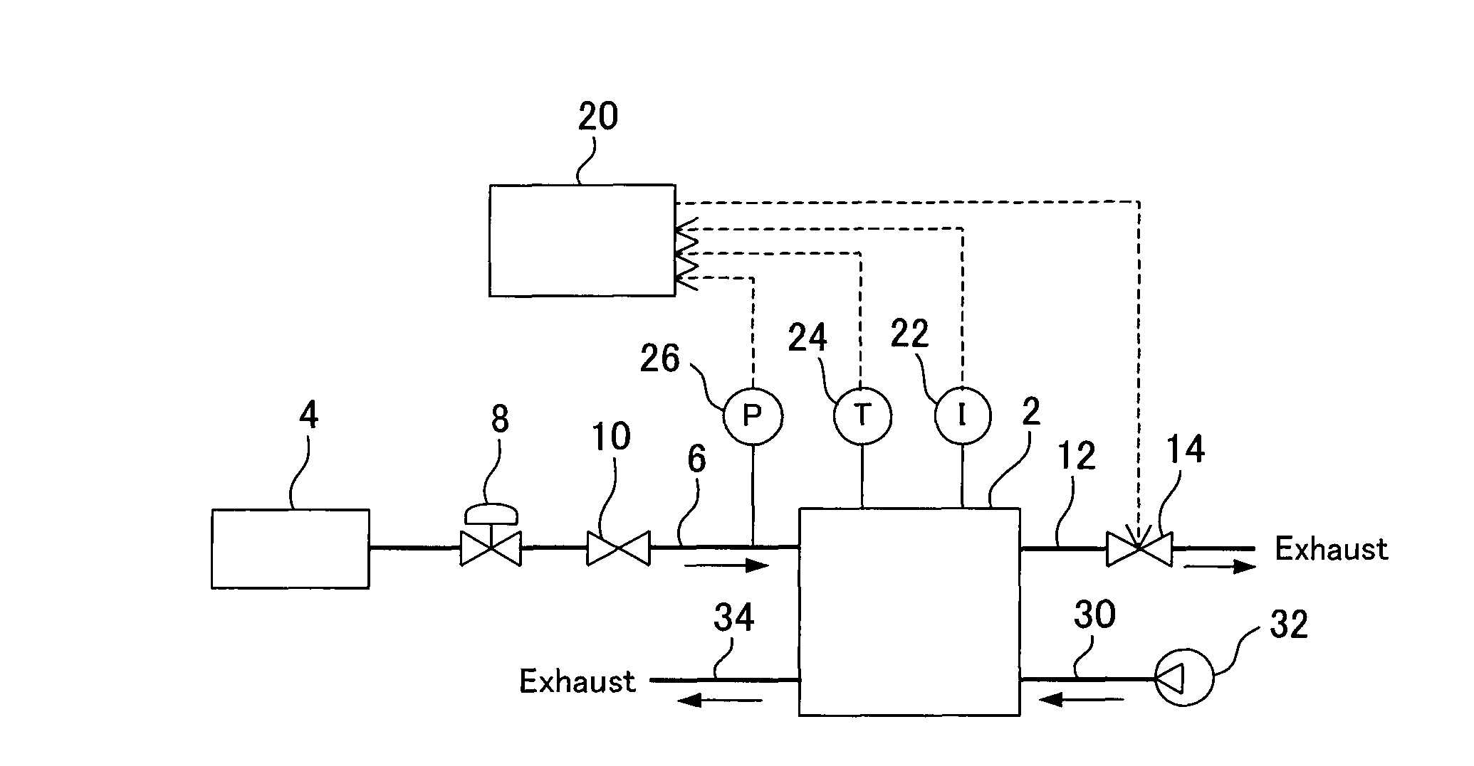
[0053]FIG. 1 is a schematic diagram showing a configuration of a fuel cell system according to the present invention. The fuel cell system supplies an electric power generated by a fuel cell 2 to a load, such as a motor. In general, the fuel cell 2 has the form of a fuel cell stack composed of a plurality of cells stacked one on another. Although not shown, each cell has a pair of current collectors and a membrane electrode assembly interposed therebetween. The membrane electrode assembly includes a solid polymer electrolyte membrane, catalyst portions formed on the both surfaces of the solid polymer electrolyte membrane, and gas diffusion layers, such as a carbon sheet, formed on the surfaces of the catalyst portions. Each current collector serves also as a separator between adjacent two membrane electrode assemblies. Each cell generates electric power using hydrogen as a...


PUM

PropertyMeasurementUnit
electric poweraaaaaaaaaa
flow rateaaaaaaaaaa
temperatureaaaaaaaaaa

Abstract

A fuel cell system includes a fuel cell, an exhaust mechanism that is connected to a downstream end of an anode gas flow channel and is capable of selecting an exhaust mode and a closed mode, a detecting device for detecting a downstream flow of an impurity in the anode gas flow channel, and a controlling device for controlling the operation of the exhaust mechanism such that the exhaust mode is selected when the magnitude of the downstream flow of the impurity meets a predetermined switching criterion and the closed mode is selected when the magnitude of the downstream flow of the impurity does not meet the switching criterion.

Description

CROSS-REFERENCE TO RELATED APPLICATIONS[0001]This application is a national phase application of International Application No. PCT / JP2008 / 051803, filed Feb. 5, 2008, and claims the priority of Japanese Application No. 2007-025904, filed Feb. 5, 2007, the contents of both of which are incorporated herein by reference.TECHNICAL FIELD[0002]The present invention relates to a fuel cell system having a fuel cell that generates an electric power using a fuel gas supplied to an anode thereof and air supplied to a cathode thereof.BACKGROUND ART[0003]As disclosed in the patent documents listed below, there are known fuel cell systems that confine the fuel gas in a gas flow channel that is in contact with the anode in the power generating surface of the fuel cell (referred to as anode gas flow channel hereinafter) during operation (referred to as anode dead end system hereinafter). In the anode dead end system, impurities, such as nitrogen and water, are accumulated in the anode gas flow chann...

Claims


Application Information

Patent Timeline
Patent Type & Authority Patents(United States)
IPC IPC(8): H01M8/04H01M8/22
CPCY02E60/50H01M8/04619H01M8/04462H01M8/04231H01M8/04761H01M8/04388H01M8/0662
Inventor KANNO, YOSHIHITO
Owner TOYOTA JIDOSHA KK
Why Eureka
Try Eureka