Lightning-protective explosion-preventive fastener

a technology of explosion prevention and fastener, which is applied in the direction of basic electric elements, electrostatic charges, aircraft lighting protectors, etc., can solve the problems of insufficient fastening force between the fastener and the fastener member, poor feedback, and insufficient fastening force, etc., to achieve excellent work stability, reduce the effect of arc suppression

Active Publication Date: 2014-04-29
MITSUBISHI AIRCRAFT
View PDF4 Cites 17 Cited by
  • Summary
  • Abstract
  • Description
  • Claims
  • Application Information

AI Technical Summary

Benefits of technology

[0017]The present invention was accomplished based on this technical problem, and has an object of providing a lightning-protective explosion-preventive fastener reliably achieving a fastening force by a fastener member and a fastening member while achieving a sufficient effect of suppressing the occurrence of an arc, the fastener also being excellent in work stability.
[0019]With this, in the insulating cover, the thicknesses (dimensions rising from the tip covering part) of the outer-circumferential-side cylindrical part and the inner-circumferential-side cylindrical part are larger than the thickness of the tip covering part. On each of the outer circumferential side and the inner circumferential side of the fastening member, a distance from the member can be sufficiently ensured with the outer-circumferential-side cylindrical part and the inner-circumferential-side cylindrical part, thereby preventing a spark due to insulation breakdown and surface discharge occurring between the fastening member and the member.
[0020]Also, the tip coating part is thinner than the outer-circumferential-side cylindrical part and the inner-circumferential-side cylindrical part. Therefore, when the fastener body and the fastening member are fastened together, the amount of deformation of the tip covering part in a thickness direction can be made small, thereby ensuring a fastening strength between the fastener body and the fastening member and preventing an impairment of tactile feedback when the fastener body and the fastening member are fastened. With this, work stability becomes excellent.
[0022]With the groove and the elongated projection fitted to each other, the insulating cover can be prevented from being removed from the fastening member.
[0028]According to the present invention, it is possible to reliably achieve a fastening force by a fastener member and a fastening member while achieving a sufficient effect of suppressing the occurrence of an arc, the fastener also being excellent in work stability.

Problems solved by technology

However, in the technology described in Japanese Patent Application Laid-Open No. 2009-227166, since the washer and and the spacer are interposed between the fastening member and the structural member, the technology has a problem such that a fastening force by the fastener member and the fastening member cannot be sufficiently achieved, providing poor feedback when the fastening member is mounted on the fastener member.
If the fastening force is increased, the washer and the spacer are crushed, and the fastening force cannot be sufficiently achieved.
Also, with the washer and the spacer being deformed at the time of fastening, tactile feedback when mounting the fastening member on the fastener member is impaired.
This makes it difficult for a worker to ascertain to which degree the fastening member is screwed into, thereby impairing work stability.
Further, if the worker forgets to mount these washer and spacer, it is disadvantageously impossible to achieve an effect of reinforcing suppression of the occurrence of an arc by interrupting current with these washer and spacer.
In such case, an electric field concentrates on an outer circumferential edge part of the fastening member, and insulation breakdown may occur between the outer circumferential edge part of the fastening member and the structural member to cause a spark.

Method used


Image

  • Lightning-protective explosion-preventive fastener
  • Lightning-protective explosion-preventive fastener
  • Lightning-protective explosion-preventive fastener

Examples


first embodiment

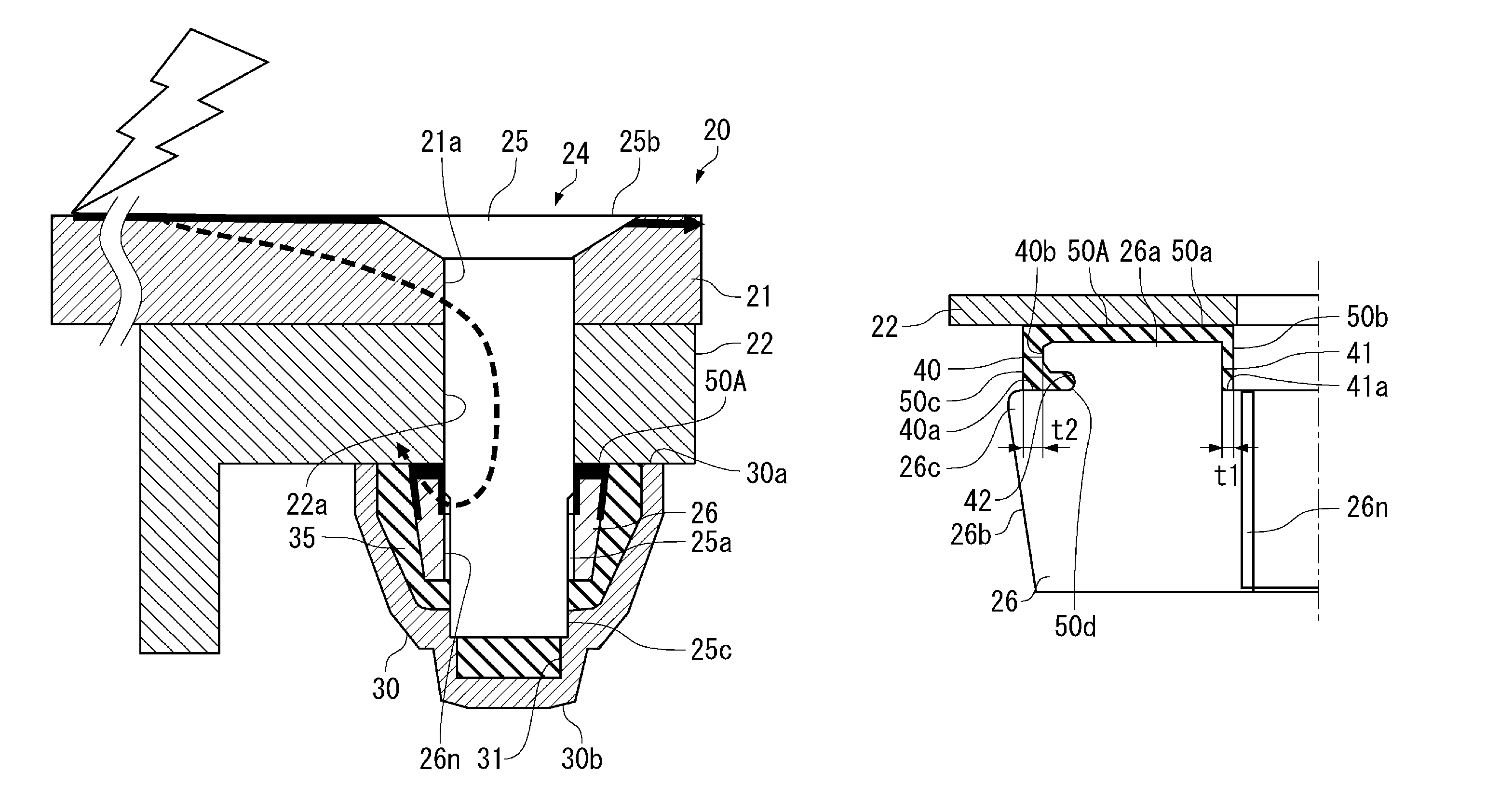
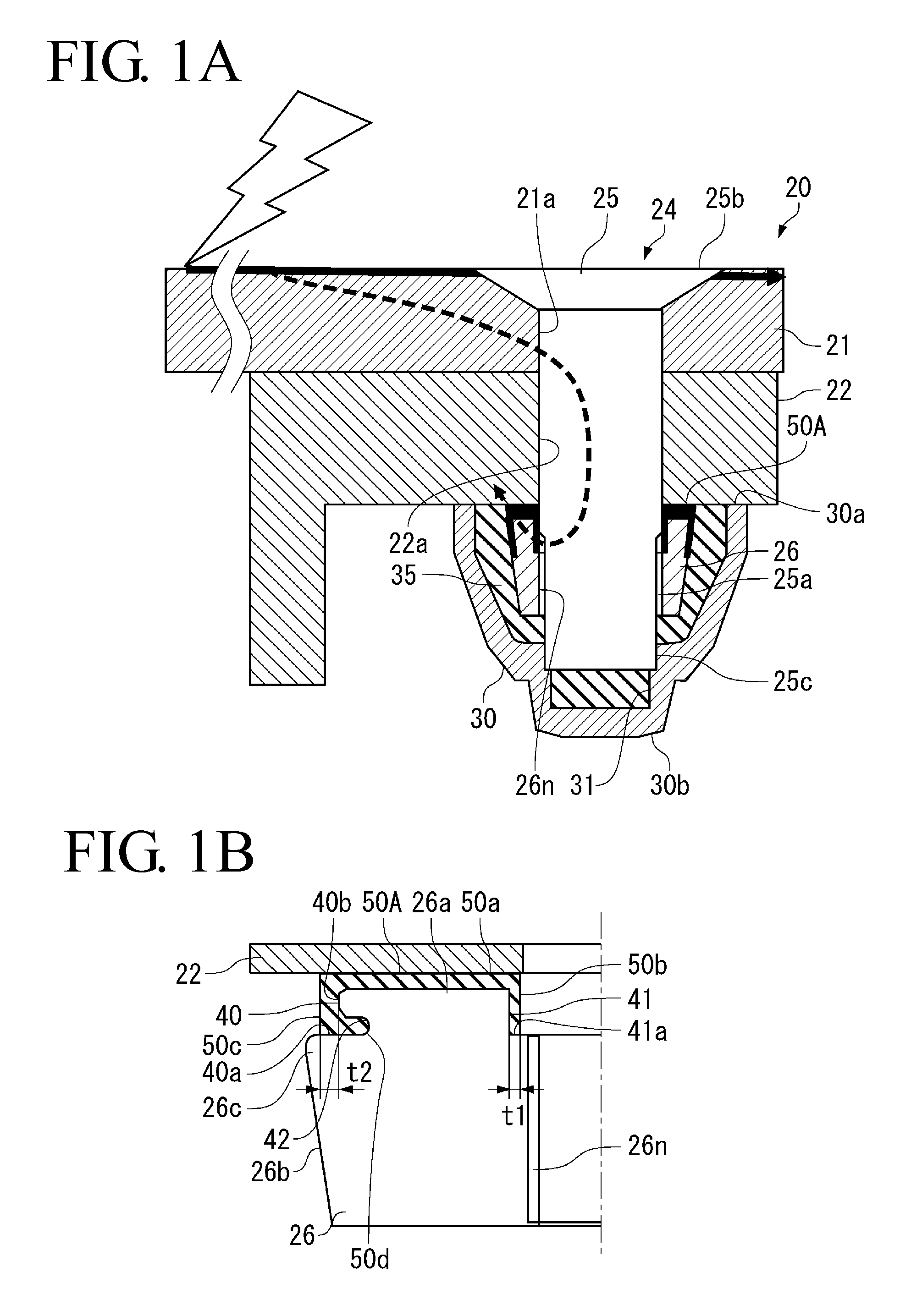
[0034]FIGS. 1A and 2A are partial sectional views of a wing configuring an airframe of an aircraft to which a lightning-protective explosion-preventive fastener in a first embodiment shown below described below is applied.

[0035]As shown in FIG. 1A, a wing (an aircraft assembly) 20 has a shell formed of a wing panel (member) 21 made of, for example, a metal material such as aluminum alloy, CFRP (Carbon Fiber Reinforced Plastics), which is a composite material made of a carbon fiber and a resin, or GFRP (Glass Fiber Reinforced Plastics), which is a composite material made of a glass fiber and a resin. A structural member for reinforcement (such as a rib), a fuel tank and various devices provided inside of the wing 20 are fixed to the wing panel 21 via a member 22 such as a stay made of a metal material such as an aluminum alloy or a composite material. The member 22 such as a stay is mounted on the wing panel 21 by a lightning-protective explosion-preventive fastener 24.

[0036]Although...

second embodiment

[0065]Next, a second embodiment of the present invention is described.

[0066]In the following, the configuration of the insulating cover 50A is different from that of the first embodiment described above, and other configurations are common to those of the first embodiment described above. Therefore, in the following, description is made mainly on the configurations different from those of the first embodiment described above, and the configurations common to the first embodiment are provided with the same reference numerals and their description is omitted.

[0067]As shown in FIG. 3, an insulating cover 50B in the present embodiment includes the tip covering part 50a covering the tip surface 26a of the fastening member 26 and abutting on the member 22, the inner-circumferential-side cylindrical part 50b rising on an inner circumferential side of the tip covering part 50a in a direction orthogonal to the tip covering part 50a and fitting in the step part 41, and an outer-circumference ...


PUM


Abstract

In an insulating cover 50A according to the present invention, a dimension of each of an outer-circumferential-side cylindrical part 50c and an inner-circumferential-side cylindrical part 50b fitting in step parts 40 and 41 in an axial direction of a fastener body 25 is set large with respect to a tip covering part 50a covering a tip surface 26a of a fastening member 26. As a result, on an outer circumferential side and an inner circumferential side of the fastening member 26, a distance from a member 22 is sufficiently ensured by the cylindrical part 50b and 50c. The tip covering part 50a is thinner than the cylindrical part 50B and 50c. Therefore, when the fastener body 25 and the fastening member 26 are fastened together, the amount of deformation of the tip covering part 50a in a thickness direction can be made small.

Description

BACKGROUND OF THE INVENTION[0001]1. Field of the Invention[0002]The present invention relates to a lightning-protective fastener to prevent explosion for use in a portion having a possibility of being filled with flammable fuel vapor of a fuel tank or the like placed in an airframe of an aircraft, in particular, a wing or a fuselage.[0003]2. Description of the Related Art[0004]A wing configuring an airframe of an aircraft generally has a hollow structure, and a wing-surface panel forming a wing surface is fixed to a structural member inside of a wing with fastener members (stoppers).[0005]Here, a fastener member has a pin-shaped fastener body inserted from outside of the wing into through holes formed on both of the wing-surface panel and the structural member inside of the wing and, with its tip fixed from inside of the wing with a fixing metal part, thereby fastening the wing-surface panel and the structural member together.[0006]In addition, also in the inside of the wing and a f...

Claims


Application Information

Patent Timeline
Patent Type & Authority Patents(United States)
IPC IPC(8): H05F3/00
CPCB64D45/02
Inventor UMEMOTO, SOICHIROYAMAKOSHI, HIDEOIYOMASA, ATSUHIROHASHIGAMI, TORU
Owner MITSUBISHI AIRCRAFT
Why Eureka
Try Eureka