Eureka AIR delivers breakthrough ideas for toughest innovation challenges, trusted by R&D personnel around the world.

Semiconductor device including antenna

a technology of electromagnetic waves and semiconductors, applied in the field of electromagnetic devices, can solve the problems of reducing the amplitude of electromagnetic waves emitted from the reader/writer, the communication distance is reduced, and the use of electromagnetic waves may occur, so as to prevent the reduction of electromagnetic waves, prevent the heating of the element forming layer, and suppress the current

Inactive Publication Date: 2014-05-06
SEMICON ENERGY LAB CO LTD
View PDF34 Cites 0 Cited by
  • Summary
  • Abstract
  • Description
  • Claims
  • Application Information

AI Technical Summary

Benefits of technology

[0006]As a result, the amplitude of electromagnetic waves emitted from the reader / writer is reduced, which causes problems such as reduction in the communication distance, and heating of the element forming layer since Joule heat is generated in the element forming layer due to a current generated in the wires and the like and a part of electromagnetic energy is used as heat energy.
[0007]In view of the foregoing, the invention provides a semiconductor device that can prevent reduction in the amplitude of electromagnetic waves transmitted from a reader / writer, and can prevent heating of an element forming layer due to a change in a magnetic field.
[0013]When wires such as a power supply wire and a ground wire are arranged in a non-circular shape, it is possible to suppress a current generated in the wires such as a power supply wire and a ground wire due to a change in a magnetic field, and to prevent reduction in the amplitude of electromagnetic waves transmitted from a reader / writer. By suppressing a current that is generated in a power supply wire and a ground wire due to a change in a magnetic field, heating of an element forming layer can be prevented.

Problems solved by technology

However, in the semiconductor device communicating data wirelessly, problems may occur in the case of using electromagnetic induction, depending on the shape of the wires and the like formed in the element forming layer 72.
As a result, the amplitude of electromagnetic waves emitted from the reader / writer is reduced, which causes problems such as reduction in the communication distance, and heating of the element forming layer since Joule heat is generated in the element forming layer due to a current generated in the wires and the like and a part of electromagnetic energy is used as heat energy.

Method used


Image

  • Semiconductor device including antenna
  • Semiconductor device including antenna
  • Semiconductor device including antenna

Examples


embodiment mode 1

[Embodiment Mode 1]

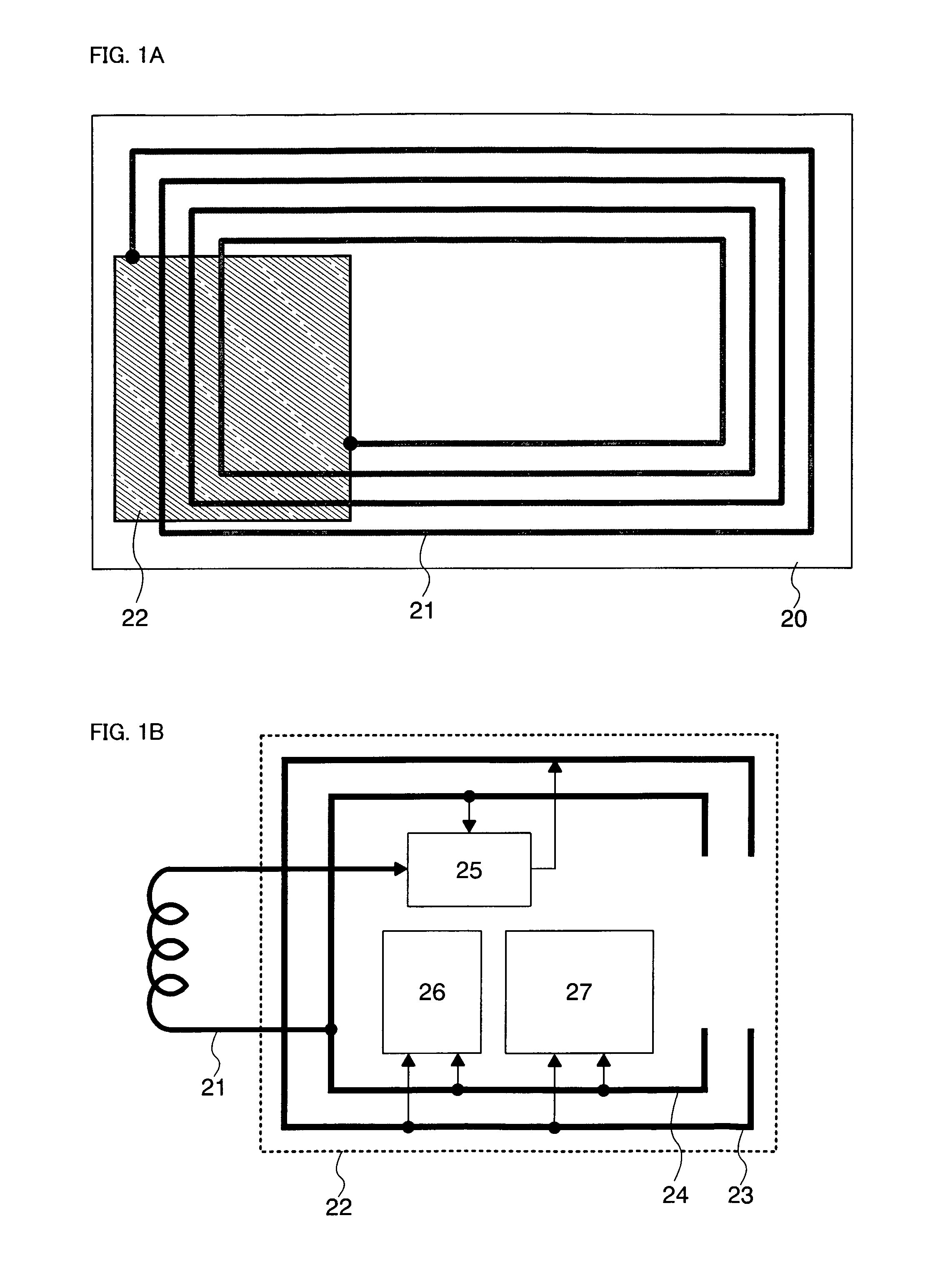
[0027]A configuration example of a semiconductor device of the invention is described with reference to FIGS. 1A and 1B. Note that FIG. 1A is a top plan view of the semiconductor device while FIG. 1B is a schematic view of an element forming layer in the semiconductor device.

[0028]As shown in FIG. 1A, the semiconductor device shown in this embodiment mode has an element forming layer 22 and an antenna 21, which are formed over a substrate 20. The element forming layer 22 and the antenna 21 may be arranged in any shape; however, they are preferably arranged so as to overlap each other in view of the reduction in size of the semiconductor device. If the antenna 21 is arranged in a coil, the element forming layer 22 is preferably arranged so as to overlap the end of the antenna 21. This is to prevent the amplitude of electromagnetic waves passing through the antenna 21 from being reduced by disposing the element forming layer 22 at the center of the antenna 21.

[0029]...

embodiment mode 2

[Embodiment Mode 2]

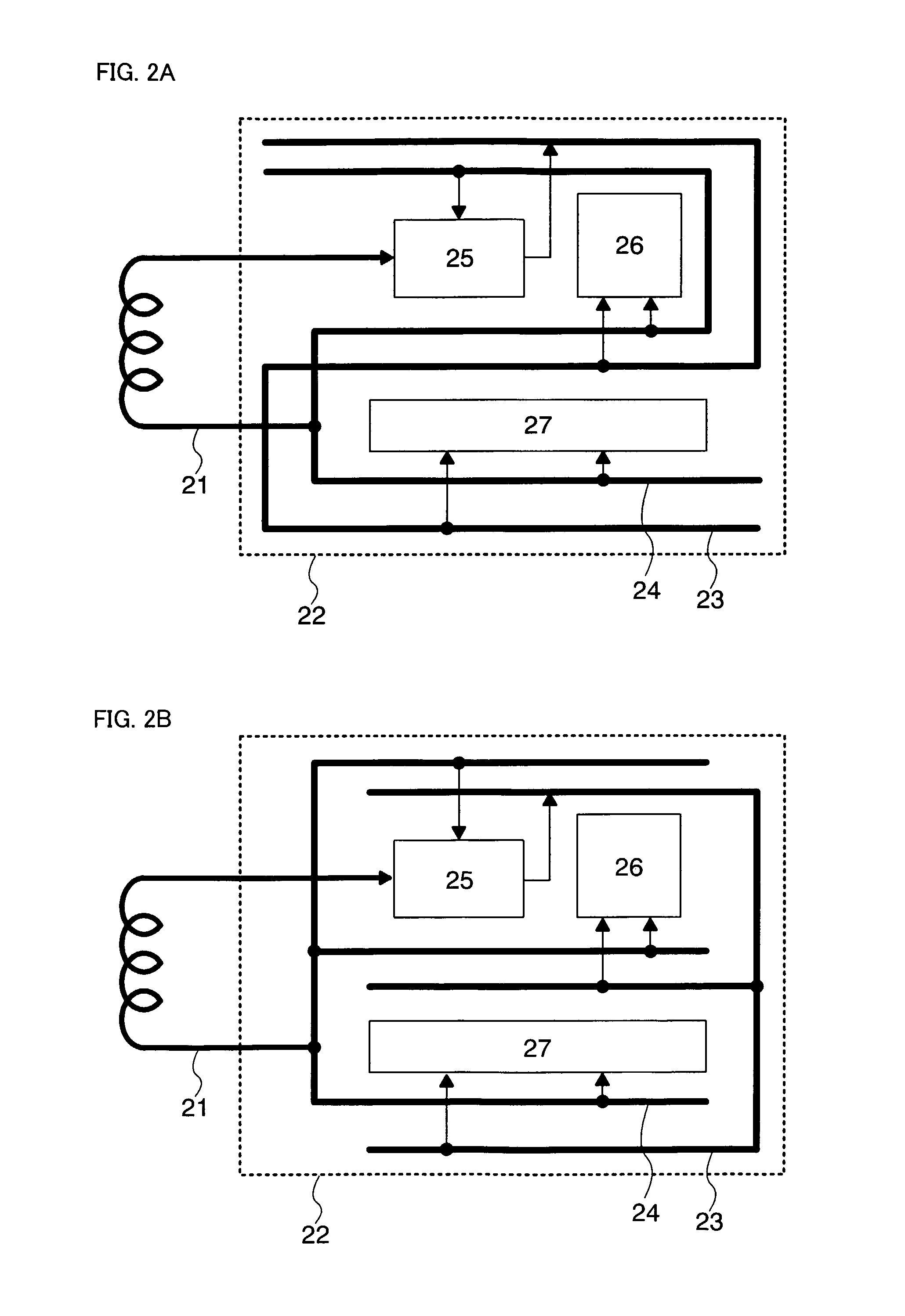
[0037]In this embodiment mode, a structure example of the semiconductor device, which is different from that shown in the aforementioned embodiment mode, is described with reference to drawings.

[0038]Described in the aforementioned embodiment mode is an example where wires such as a power supply wire and a ground wire, which are arranged in a circular shape so as to surround functional circuits and the like, are partially cut off to be formed into a U-shape. However, the invention is not limited to this, and wires such as a power supply wire and a ground wire may be arranged in any shape as long as it is not influenced by a change in a magnetic field. Specific examples different from that shown in the aforementioned embodiment mode are described below with reference to the drawings.

[0039]In FIGS. 2A and 2B, the power supply wire 23 and the ground wire 24 are provided so as to pass between the power supply circuit 25 and the functional circuits 26 and 27. In FIG. 2...

embodiment mode 3

[Embodiment Mode 3]

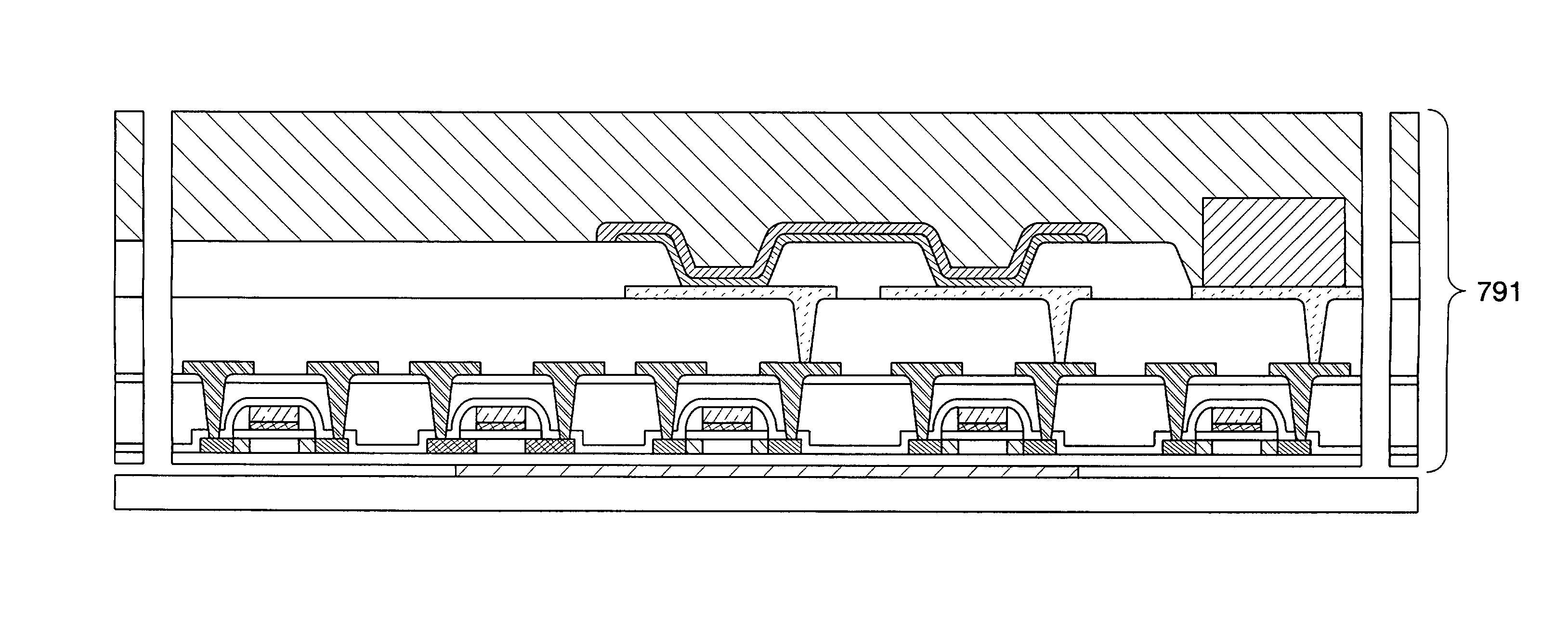
[0046]In this embodiment mode, an example of manufacturing steps of the semiconductor device of the invention is described with reference to drawings. Specifically shown is an example of manufacturing a semiconductor device using a thin film transistor (TFT) as a transistor on an element forming layer by a separating method where a TFT is provided over a support substrate and then separated therefrom.

[0047]First, a separation layer 702 is formed over a surface of a substrate 701 (FIG. 6A). The substrate 701 may be a glass substrate, a quartz substrate, a metal substrate such as stainless having a surface over which an insulating film is formed, a plastic substrate having heat resistance to the processing temperature of the steps, or the like. Such a substrate 701 has no limit in terms of size and shape. Accordingly, for example, if a rectangular substrate with each side of one meter or more is used for the substrate 701, productivity can be dramatically increased....


PUM


Abstract

A semiconductor device that can prevent reduction in the amplitude of electromagnetic waves transmitted from a reader / writer, and can prevent heating of an element forming layer due to a change in a magnetic field. The semiconductor device of the invention has an element forming layer formed over a substrate, and an antenna connected to the element forming layer. The element forming layer has at least wires such as a power supply wire and a ground wire that are arranged in a non-circular shape. The element forming layer and the antenna may be provided so as to overlap each other at least partially. The antenna may be provided above or below the element forming layer.

Description

TECHNICAL FIELD[0001]The present invention relates to a semiconductor device capable of communicating data wirelessly.BACKGROUND ART[0002]In recent years, identification technology where an ID (identification number) is assigned to each object so as to reveal data thereon such as the history has been attracting attention, which is utilized for production management and the like. Above all, semiconductor devices capable of communicating data wirelessly have been developed. Such semiconductor devices include an RFID (Radio Frequency Identification) tag (also called an ID tag, an IC tag, an IC chip, an RF (Radio Frequency) tag, a wireless tag, an electronic tag, or a wireless chip), and the like have been introduced into companies, the market and the like.[0003]In general, many of RFID tags that have been put into practical use so far have, for example, as shown in FIG. 4A, a configuration where an element forming layer 72 (also called an IC (Integrated Circuit) chip) including a circu...

Claims


Application Information

Patent Timeline
Patent Type & Authority Patents(United States)
IPC IPC(8): H01L21/02
CPCH01L27/12G06K19/0701G06K19/07749H01L21/84
Inventor KATO, KIYOSHIMORIYA, YOSHITAKA
Owner SEMICON ENERGY LAB CO LTD
Why Eureka
Eureka Blog
Learn More